
The Hidden Challenges of Multi-Peripheral Servo Integration
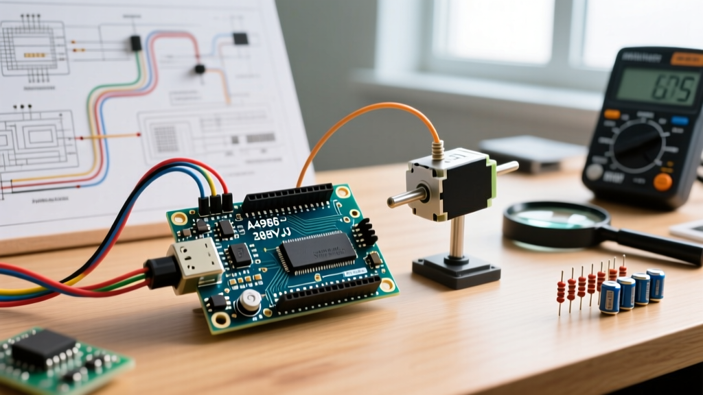
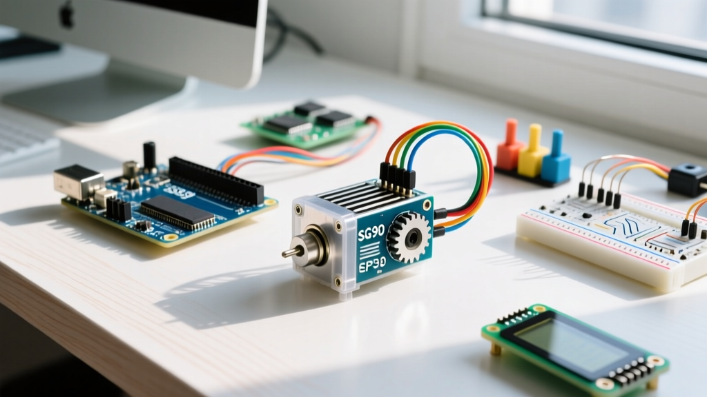
The Tower Pro SG90 is arguably the most ubiquitous micro-servo in the DIY electronics ecosystem. In 2026, genuine units hover around $2.50 to $3.50, while high-quality clones with metal gear upgrades (often labeled MG90S) can be sourced for $1.50 to $2.00 in bulk. However, while blinking an LED or sweeping a single servo is trivial, integrating an arduino sg90 servo motor into a complex, multi-peripheral setup introduces severe architectural bottlenecks. When you add an SSD1306 OLED display, an HC-SR04 ultrasonic sensor, and a relay module to the same breadboard, the SG90 often becomes the catalyst for system-wide instability.
This guide bypasses basic tutorials and dives deep into the electrical engineering realities of power budgeting, timer conflicts, and signal integrity when deploying the SG90 alongside other demanding peripherals.
Arduino SG90 Servo Motor: Electrical Specifications and Real-World Draw
Before designing your power architecture, you must understand the SG90's actual electrical footprint. The datasheet provides baseline numbers, but real-world stall conditions tell a different story.
| Parameter | Datasheet Value | Real-World Multi-Peripheral Impact |
|---|---|---|
| Operating Voltage | 4.8V - 6.0V | Will stutter below 4.5V; brownout risk on shared 5V rails. |
| Stall Current | ~650mA | Can instantly trip USB overcurrent protection or sag an LDO. |
| No-Load Current | ~10mA - 50mA | Negligible, but multiplies if using arrays of servos. |
| PWM Frequency | 50Hz (20ms period) | Requires precise timer interrupts; conflicts with software PWM. |
| Pulse Width | 500µs - 2400µs | Maps to 0° - 180°. Exceeding 2400µs risks internal hard-stops. |
Power Architecture: Preventing Brownouts in Complex Builds
The most common point of failure in multi-peripheral setups is the microcontroller's onboard voltage regulator. If you are using a classic Arduino Uno R3, the onboard NCP1117 5V linear regulator is rated for roughly 800mA, but practically it can only dissipate enough heat to supply about 400mA-500mA continuously before thermal shutdown. If your SG90 hits a mechanical bind and draws 650mA while your OLED and sensors are drawing another 100mA, the 5V rail will collapse. This causes the microcontroller to reset, corrupting I2C transactions and freezing your code.
Expert Rule of Thumb: Never power an inductive load like the SG90 directly from a microcontroller's 5V output pin when operating a multi-peripheral bus. Always use a dedicated power delivery circuit.
The BEC Solution for Clean Power
To isolate the servo's current spikes from your logic circuits, use a 3A UBEC (Universal Battery Eliminator Circuit) or a dedicated 5V buck converter module (like the LM2596-based boards, which cost around $1.50). Wire the servo's red and brown wires directly to the BEC's 5V and GND outputs. Crucially, you must tie the BEC's ground to the microcontroller's ground to establish a common reference voltage for the PWM signal.
Resolving PWM and Timer Conflicts
When your setup includes multiple peripherals, software resources become just as constrained as hardware power. The standard Arduino Servo Library Documentation reveals a critical limitation for AVR-based boards (Uno, Nano, Mega): the library hijacks Timer1 to generate the 50Hz signal.
The Timer1 Clash
Because Timer1 is disabled for standard PWM use when the Servo library is active, pins 9 and 10 on the Arduino Uno will lose their analogWrite() functionality. If your multi-peripheral setup includes a DC motor driver or an RGB LED relying on those specific pins, your hardware will fail silently. Furthermore, libraries that rely on Timer1 for high-speed I2C or specific interrupt routines will crash.
Offloading to I2C: The PCA9685 Advantage
For robust multi-peripheral integration, especially when using ESP32 or modern ARM Cortex-M boards where timer allocation is complex, offload the PWM generation to an external I2C driver. The NXP PCA9685 16-channel PWM driver (widely available on breakout boards for ~$2.50) communicates via I2C and handles the 50Hz timing in hardware. As detailed in the Adafruit PCA9685 16-Channel Servo Driver Guide, this frees up your microcontroller's CPU cycles and eliminates timer conflicts entirely, allowing you to run complex sensor fusion algorithms without servo jitter.
Step-by-Step: Wiring the SG90 Alongside I2C and Echo Sensors
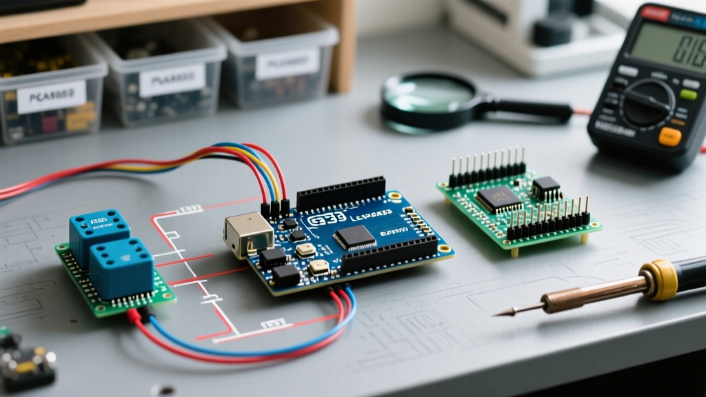
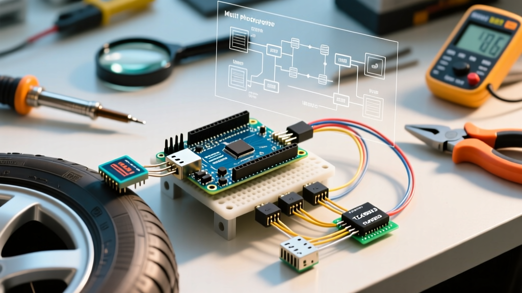
Let's map out a reliable wiring topology for an Arduino Uno R4 Minima running an SG90, a 0.96" SSD1306 OLED (I2C), and an HC-SR04 Ultrasonic Sensor.
- Establish Common Ground: Connect the GND pin of the Arduino, the GND of the external 5V Buck Converter, the OLED GND, and the HC-SR04 GND to a single, unified ground bus on your breadboard. Ground loops cause signal jitter.
- Route I2C Lines: Connect the OLED SDA to A4 and SCL to A5 (or the dedicated I2C header on the R4). Keep these wires short and away from the servo's power cables to prevent inductive noise coupling.
- Isolate the Echo Pin: The HC-SR04 Echo pin outputs 5V. If you are using a 3.3V logic board (like an ESP32 or Arduino Due), use a voltage divider (e.g., 1kΩ and 2kΩ resistors) to step the Echo signal down to 3.3V. The SG90 signal wire (Orange/Yellow) can connect directly to a 5V-tolerant digital pin (e.g., Pin 6).
- Power Injection: Connect the 5V Buck Converter output strictly to the SG90 VCC (Red) and the HC-SR04 VCC. Power the OLED from the microcontroller's 3.3V or 5V pin, as its draw is minimal (~20mA).
Troubleshooting Jitter, Noise, and Gear Stripping
Even with perfect wiring, multi-peripheral environments introduce edge cases that cause the SG90 to misbehave. Here is how to diagnose and fix the most common failure modes.
1. Micro-Stutters and Position Drift
The Symptom: The servo holds its position but vibrates slightly, or drifts a few degrees over time.
The Root Cause: The SG90 uses an internal resistive wiper (potentiometer) to read the output shaft position. In cheap clones, this wiper accumulates carbon dust or suffers from poor contact, sending noisy voltage feedback to the internal comparator IC. Additionally, high-frequency noise from I2C OLED refresh cycles can bleed into the PWM signal line.
The Fix: Implement a software deadband. Instead of commanding the servo to exact microsecond values continuously, only send a new pulse width if the target angle changes by more than 2 degrees. Furthermore, ensure your PWM signal wire is not routed parallel to your I2C SCL line.
2. The "Hard Stop" Gear Strip
The Symptom: A grinding noise followed by a complete loss of torque.
The Root Cause: The SparkFun Servo Motor Tutorial warns against commanding servos beyond their mechanical limits. The SG90's internal physical hard-stops occur around 0° and 180°. If your code commands 0° (typically 500µs) but the physical mechanism binds at 5°, the motor will continue pushing against the plastic end-stop, drawing stall current and stripping the nylon gears.
The Fix: Calibrate your specific servo. Use a calibration sketch to find the exact microsecond values where your servo's physical movement stops, and map your software constraints to those safe boundaries (e.g., 550µs to 2350µs) rather than the theoretical 500-2400µs limits.
3. USB Disconnects During Sweeps
The Symptom: When the servo starts moving, the Arduino disconnects from the PC IDE, and the serial monitor drops.
The Root Cause: The transient current spike of the SG90 starting under load exceeds the 500mA limit of standard USB 2.0 ports, triggering the host PC's overcurrent protection or resetting the Arduino's onboard polyfuse.
The Fix: Power the Arduino via the DC barrel jack (with a 7-9V adapter) or use a powered USB hub rated for 2A+ per port, while keeping the servo on its own dedicated BEC.
Final Thoughts on Peripheral Synergy
Successfully deploying an arduino sg90 servo motor in a dense, multi-peripheral environment requires shifting your mindset from simple component wiring to holistic system architecture. By respecting power budgets, offloading timer-critical PWM tasks to dedicated I2C hardware, and understanding the physical limitations of the SG90's internal feedback loop, you can build robust, jitter-free robotic systems that operate reliably in the real world.