
The Evolution of Arduino LCD Interfacing
Learning how to connect a LCD display to Arduino is a foundational milestone for any embedded systems developer. While high-resolution TFT and OLED screens have dropped in price by 2026, the classic 16x2 character LCD (based on the Hitachi HD44780 controller) remains the undisputed industry standard for high-visibility, low-power industrial dashboards, outdoor weather stations, and DIY appliance interfaces. Its parallel interface is robust, its sunlight readability is excellent, and its power draw is minimal.
Historically, wiring these displays required sacrificing up to six digital GPIO pins. Today, the integration of an I2C backpack (typically utilizing the PCF8574 I/O expander) has reduced this to just two pins, freeing up your microcontroller for sensors and actuators. This guide covers both the modern I2C standard and the legacy 4-bit parallel method, providing the exact schematics, code, and edge-case troubleshooting required for a flawless deployment.
Hardware Bill of Materials (BOM) & Pricing
Before soldering, ensure you have the correct components. Prices reflect average 2026 market rates for hobbyist-grade components.
| Component | Model / Specification | Est. Price (USD) | Notes |
|---|---|---|---|
| Character LCD | 16x2 HD44780 (QC1602A) | $3.50 - $5.00 | Standard 16-pin parallel interface |
| I2C Backpack | PCF8574T or PCF8574AT | $1.20 - $2.00 | Reduces wiring to 4 pins (VCC, GND, SDA, SCL) |
| Contrast Potentiometer | 10kΩ Linear Taper (B10K) | $0.50 | Required ONLY for parallel wiring method |
| Microcontroller | Arduino Uno R3 / R4 Minima | $25.00 - $30.00 | ATmega328P or Renesas RA4M1 based |
Method 1: The Modern Standard (I2C Backpack Wiring)
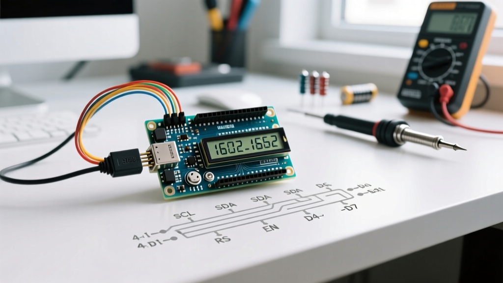
Using an I2C backpack is the recommended approach for 95% of modern projects. It utilizes the Inter-Integrated Circuit protocol, requiring only the SDA (Serial Data) and SCL (Serial Clock) lines alongside power and ground.
Pinout & Connections
- GND: Connect to Arduino GND.
- VCC: Connect to Arduino 5V. Warning: Do not use 3.3V. The HD44780 logic and backlight require 4.5V to 5.5V for stable operation.
- SDA: Connect to Arduino A4 (on Uno R3) or the dedicated SDA pin (on Uno R4 / Nano ESP32).
- SCL: Connect to Arduino A5 (on Uno R3) or the dedicated SCL pin.
Pro-Tip for Long Cable Runs: The I2C protocol is sensitive to capacitance. If your I2C cable exceeds 30cm, the internal pull-up resistors on the Arduino (typically 20kΩ-50kΩ) will be too weak, resulting in corrupted data. Solder external 4.7kΩ pull-up resistors between the SDA/SCL lines and the 5V rail to ensure signal integrity.
The I2C Address Trap: PCF8574 vs PCF8574A
The most common failure point when learning how to connect a LCD display to Arduino via I2C is an address mismatch. Backpacks use either the NXP PCF8574T or the PCF8574AT chip. According to the NXP PCF8574 Datasheet, the base addresses differ:
- PCF8574T: Base address is
0x20. With the default jumper settings (A0, A1, A2 pulled HIGH), the address is0x27. - PCF8574AT: Base address is
0x38. With default jumper settings, the address is0x3F.
If your backlight turns on but no text appears, your code is likely polling the wrong address. Use the standard Arduino I2C Scanner sketch to poll the bus and verify the exact hexadecimal address before initializing your display library.
Method 2: Legacy 4-Bit Parallel Wiring (HD44780)
If you are out of I2C addresses or working with a barebones ATmega328P chip on a breadboard, direct parallel wiring is necessary. We use 4-bit mode instead of 8-bit mode. The HD44780 controller can accept data in 4-bit nibbles, which cuts the required data pins in half with zero perceptible latency for human-readable text updates.
The 16-Pin Challenge
| LCD Pin | Function | Arduino Connection |
|---|---|---|
| 1 (VSS) | Ground | GND |
| 2 (VDD) | Logic Power | 5V |
| 3 (V0) | Contrast Adjust | Wiper of 10kΩ Potentiometer |
| 4 (RS) | Register Select | Digital Pin 12 |
| 5 (RW) | Read/Write | GND (Force Write Mode) |
| 6 (E) | Enable | Digital Pin 11 |
| 11-14 (D4-D7) | Data Lines | Digital Pins 5, 4, 3, 2 |
| 15 (A) | Backlight Anode | 5V (via 100Ω resistor) |
| 16 (K) | Backlight Cathode | GND |
Contrast Calibration (The #1 Failure Point)
Pin 3 (V0) controls the liquid crystal bias voltage. If left floating, the display will show nothing. If tied directly to GND, you will see a row of solid black blocks. You must wire a 10kΩ potentiometer with the outer legs to 5V and GND, and the middle wiper to V0. Adjust the knob until the black blocks just disappear, leaving a clear, high-contrast background.
Arduino Code Implementation
For both methods, we rely on established libraries. Refer to the Arduino Official LiquidCrystal Reference for advanced API methods.
I2C Code (LiquidCrystal_I2C Library)
Install the LiquidCrystal_I2C library by Frank de Brabander via the Arduino Library Manager.
#include <Wire.h>
#include <LiquidCrystal_I2C.h>

// Initialize with address 0x27, 16 columns, 2 rows
LiquidCrystal_I2C lcd(0x27, 16, 2);

void setup() {
  lcd.init();
  lcd.backlight();
  lcd.setCursor(0, 0);
  lcd.print("ElectricalFlux");
  lcd.setCursor(0, 1);
  lcd.print("I2C LCD Guide");
}

void loop() {
  // Static display for demo
}
Parallel Code (Native LiquidCrystal Library)
#include <LiquidCrystal.h>

// Initialize: (RS, E, D4, D5, D6, D7)
LiquidCrystal lcd(12, 11, 5, 4, 3, 2);

void setup() {
  lcd.begin(16, 2);
  lcd.print("Parallel Wiring");
}

void loop() {
  lcd.setCursor(0, 1);
  lcd.print("Millis: ");
  lcd.print(millis() / 1000);
  delay(500);
}
Advanced E-E-A-T: Custom Character Generation (CGRAM)
The HD44780 controller features 64 bytes of Character Generator RAM (CGRAM), allowing you to define up to eight custom 5x8 pixel characters. This is essential for creating battery indicators, signal bars, or custom arrows without relying on external graphical displays.
Use a visual LCD character creator tool to generate the byte arrays. Here is how to implement a custom 'Thermometer' icon:
byte thermometer[8] = {
  B00100,
  B01010,
  B01010,
  B01010,
  B01010,
  B10001,
  B11111,
  B01110
};

void setup() {
  lcd.createChar(0, thermometer);
  lcd.write(0); // Prints the custom character
}
Troubleshooting Matrix: Common Failure Modes
Even experienced engineers encounter edge cases when integrating character displays. Use this diagnostic matrix to resolve issues rapidly.
| Symptom | Root Cause | Engineering Fix |
|---|---|---|
| Backlight ON, solid white blocks on Row 1 | Contrast voltage (V0) is too high or uninitialized. | Adjust 10kΩ pot. For I2C, turn the tiny blue trimpot on the backpack PCB. |
| Backlight ON, completely blank screen | RW pin floating (Parallel) or I2C address mismatch. | Tie RW to GND. Run I2C Scanner sketch to verify 0x27 vs 0x3F. |
| Text displays backwards or scrambled | Data lines (D4-D7) mapped in reverse order in code. | Verify physical wiring matches the exact pin order in the LiquidCrystal constructor. |
| Display flickers during motor actuation | Voltage brownout on the 5V rail due to motor current spikes. | Isolate LCD VCC and Backlight Anode to a dedicated 5V buck converter, sharing only GND with the Arduino. |
| Backlight jumper missing on I2C board | Some PCF8574 boards have a 2-pin jumper near the VCC pin to enable the backlight circuit. | Short the two jumper pins with a jumper cap or solder bridge. |
Summary
Understanding how to connect a LCD display to Arduino bridges the gap between basic microcontroller logic and user-facing hardware. While the 4-bit parallel method offers a deep dive into multiplexed data buses and register selection, the I2C backpack method represents the modern standard for efficient GPIO management. By paying strict attention to I2C addressing variants, contrast bias calibration, and power rail isolation, you can ensure your HD44780 displays operate flawlessly in any embedded environment.
For further reading on character LCD architectures and I2C bus capacitance limits, consult the Adafruit Character LCD Wiring Guide and official NXP silicon documentation.