
From Breadboard to Bus Stop: A Commercial-Grade Transit Display
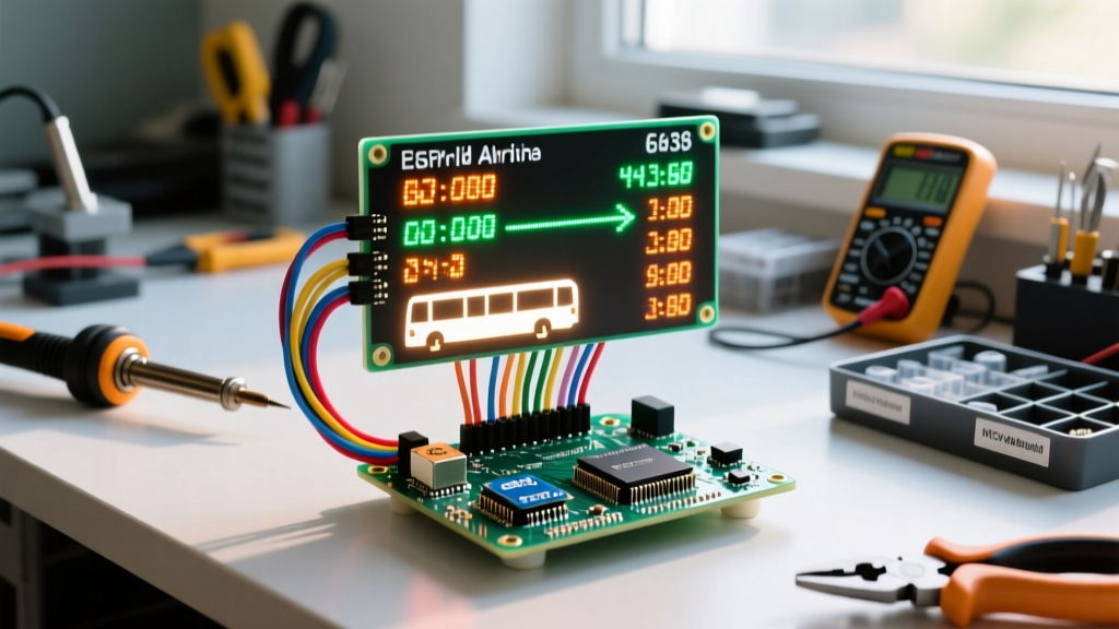
Scrolling text displays are a rite of passage for electronics hobbyists, but transitioning a prototype into a reliable, real-world application requires navigating power constraints, environmental hazards, and data latency. In this guide, we will build a live Passenger Information Display (PID) using an Arduino and LED matrix hardware stack. Specifically, we are designing a smart bus stop sign that fetches real-time arrival data via Wi-Fi and scrolls it across a high-visibility dot matrix display.
Unlike basic tutorials that rely on hardcoded strings and USB power, this build utilizes the General Transit Feed Specification (GTFS) to pull live municipal transit data. We will address the common failure modes of the MAX7219 driver chips, solve SPI signal degradation over long wire runs, and design an enclosure capable of surviving outdoor temperature swings.
Bill of Materials and 2026 Cost Breakdown
Building a robust outdoor display requires components that can handle continuous operation. The prices below reflect early 2026 market rates for hobbyist-to-prosumer grade components.
| Component | Model / Specification | Est. Price (2026) | Purpose |
|---|---|---|---|
| Microcontroller | Arduino Uno R4 WiFi | $27.50 | Wi-Fi connectivity, 5V logic, 48MHz Cortex-M4 |
| Display | FC-113 MAX7219 4-in-1 Matrix (32x8) | $14.00 | High-contrast red LED dot matrix |
| Power Supply | Mean Well 5V 4A Switching PSU (LRS-25-5) | $18.50 | Stable bulk power for LED peaks |
| Logic Shifter | 74HCT125 Quad Buffer IC | $1.20 | SPI signal conditioning |
| Enclosure | IP65 Polycarbonate Box (150x100x50mm) | $32.00 | UV and weather resistance |
| Passives | 1000µF 16V Capacitors, Cable Glands | $4.50 | Decoupling and waterproofing |
Total Estimated Hardware Cost: ~$97.70. This is significantly cheaper than commercial PID units, which often exceed $800 per installation.
Hardware Architecture and Power Delivery
The most frequent point of failure in Arduino and LED matrix projects is power starvation. A standard 32x8 LED matrix contains 256 individual LEDs. If all LEDs are illuminated at maximum intensity simultaneously, the array can draw upwards of 1.5A to 2A. The onboard 5V regulator of a standard Arduino Uno will thermally throttle or fail if subjected to this load.
Isolating Logic from High-Current Loads
We use a dedicated 5V 4A Mean Well switching power supply. The 5V line is wired directly to the VCC pins of the MAX7219 matrix modules. The Arduino Uno R4 WiFi is powered via its 5V pin (bypassing the onboard regulator) or via USB from a separate isolated buck converter tied to the main PSU.
Expert Decoupling Rule: You must solder a 1000µF electrolytic capacitor directly across the VCC and GND input pins of the first matrix module in the chain. The MAX7219 chips multiplex the LEDs at high frequencies; without bulk local capacitance, the rapid current switching will cause voltage sags that reset the Arduino's microcontroller via the shared ground plane.
Wiring the SPI Bus for Signal Integrity
The MAX7219 communicates via SPI (Serial Peripheral Interface). According to the Arduino SPI Communication Guide, the Uno R4 uses hardware SPI pins for maximum throughput. However, real-world wiring introduces capacitance and noise.
- VCC: 5V (From Mean Well PSU)
- GND: Common Ground (PSU, Arduino, and Matrix must share this)
- DIN (MOSI): Pin 11 on Uno R4
- CS (SS): Pin 10 on Uno R4
- CLK (SCK): Pin 13 on Uno R4
Solving the 'Ghosting' and Flickering Edge Case
If you use standard 20cm Dupont jumper wires to connect the Arduino to the matrix, you will likely encounter 'ghosting' (faint illumination of adjacent LEDs) or random flickering. This occurs because long, unshielded wires act as antennas, picking up EMI and increasing the capacitance of the SPI CLK line, which rounds off the square wave edges.
The Solution: Keep SPI traces under 10cm. If the physical layout requires longer runs, insert a 74HCT125 logic buffer IC near the matrix input to re-sharpen the SPI clock edges. Furthermore, ensure the SPI clock speed in your software initialization does not exceed 4MHz for runs longer than 15cm.
Software: Parsing GTFS-Realtime Data
To make this a true real-world application, we avoid hardcoded strings. Municipal transit authorities publish live arrival data using GTFS-Realtime, typically encoded in Protocol Buffers (Protobuf).
Because parsing Protobuf natively on a microcontroller is memory-intensive, the best architectural pattern for 2026 IoT projects is to use a middleware server (like a Raspberry Pi or a cheap cloud VPS) to parse the GTFS feed and expose a lightweight JSON API. The Arduino Uno R4 WiFi simply performs an HTTP GET request to fetch a JSON string containing the next two bus arrivals.
Scrolling Logic with MD_Parola
For rendering the text, the MD_Parola and MD_MAX72XX libraries remain the industry standard for hobbyist matrix displays.
When initializing the display, you must define the hardware type. Most cheap FC-113 modules use the FC16_HW configuration. If your text scrolls backward or upside down, it is almost always a mismatch in the hardware enum definition, not a wiring fault.
Note on Intensity: The Analog Devices MAX7219 Datasheet specifies that setting the intensity register to maximum (15) drastically increases heat output. For outdoor displays in direct sunlight, an intensity of 12 is usually sufficient and reduces thermal load by roughly 40%.
Real-World Failure Modes and Troubleshooting
Deploying electronics outdoors introduces variables that breadboard testing cannot replicate. Here are the most common edge cases and their engineered solutions:
1. Thermal Throttling and Heat Soak
The MAX7219 is a linear driver, meaning it dissipates excess voltage as heat. In a sealed IP65 polycarbonate enclosure, ambient temperatures can easily exceed 50°C (122°F) on a sunny day, causing the ICs to overheat and shut down via their internal thermal protection.
Fix: Apply a small aluminum finned heatsink (14x14x6mm) to the MAX7219 chips using thermally conductive epoxy. Additionally, line the inside of the enclosure's front panel with reflective mylar tape to deflect IR radiation from the sun.
2. Internal Condensation
IP65 enclosures keep liquid water out, but they do not stop water vapor. When the temperature drops at night, moisture trapped inside the sealed box during assembly will condense on the PCB, leading to short circuits and corrosion on the SPI pins.
Fix: Drill a small 3mm vent hole at the bottom of the enclosure and cover it with a breathable, waterproof Gore-Tex membrane vent plug. Place two 5-gram silica gel desiccant packs inside the housing to absorb residual moisture.
3. Wi-Fi Reconnection Failures
The ESP32-S3 module on the Uno R4 WiFi occasionally drops connections when polling a router with high client counts. If the HTTP GET request times out, the display can freeze on the last known arrival time, misleading passengers.
Fix: Implement a hardware watchdog timer (WDT) in your Arduino sketch. If the Wi-Fi stack hangs for more than 60 seconds, the WDT forces a hard reboot. Furthermore, display a visual indicator (like a slowly blinking dot in the bottom right corner) that pulses only when a successful API handshake occurs, allowing maintenance crews to verify connectivity at a glance.
Conclusion
Building a reliable transit sign with an Arduino and LED matrix bridges the gap between simple prototyping and industrial IoT deployment. By respecting the power requirements of the MAX7219, conditioning your SPI signals, and engineering for thermal and environmental extremes, you can create a highly visible, low-cost passenger information system that operates flawlessly in the real world. Whether deployed at a private corporate shuttle stop or a community transit hub, this architecture provides a robust foundation for dynamic public data display.