
The Gold Standard of Digital Thermometry
When precision, noise immunity, and long cable runs are required, the DS18B20 temperature sensor with Arduino remains the undisputed champion of microcontroller interfacing. Unlike analog NTC thermistors that suffer from voltage drop and ADC non-linearity, the DS18B20 digitizes the temperature directly at the probe head, transmitting a robust digital signal via Maxim Integrated's (now Analog Devices) proprietary 1-Wire protocol.
In this comprehensive wiring and code guide, we move beyond basic tutorials. We will dissect 1-Wire bus capacitance, tackle the rampant counterfeit chip crisis of 2026, and provide production-ready C++ code for addressing multiple sensors on a single data line.
Hardware Variants and the Counterfeit Crisis
Before wiring your circuit, you must verify your hardware. The DS18B20 is primarily available in two packages:
- TO-92 Transistor Package: Ideal for breadboarding and PCB integration. Measures ambient air temperature with a ~15-second thermal time constant.
- Waterproof Stainless Steel Probe: Housed in a sealed 304 stainless steel tube (typically 6mm x 30mm) with a 1-meter braided cable. Perfect for hydroponics, soil sensing, and liquid monitoring.
Identifying Genuine vs. Clone Sensors
As of 2026, the market is saturated with counterfeit DS18B20 chips. Genuine Analog Devices DS18B20+ sensors cost between $3.50 and $4.50 on authorized distributors like DigiKey or Mouser. Conversely, marketplaces offer clones for as little as $0.60.
Expert Warning: Counterfeit chips often fail catastrophically above 80°C, exhibit a 2°C offset error, or falsely report 12-bit resolution while actually operating in 9-bit mode. For any deployment where safety or scientific accuracy is critical, always source from authorized distributors.
1-Wire Bus Physics and Pull-Up Resistor Selection
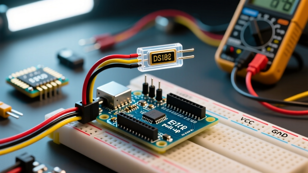
The 1-Wire protocol relies on an open-drain architecture. The Arduino releases the data line to let it float high, and the sensor pulls it low to transmit data. This requires a pull-up resistor connected to VCC. While 4.7kΩ is the default recommendation, it is not universally optimal.
As cable length increases, so does the parasitic capacitance of the wire. A 4.7kΩ resistor paired with a 20-meter cable will result in sluggish rise times, causing CRC (Cyclic Redundancy Check) failures and corrupted data.
| Cable Length | Bus Capacitance (Est.) | Recommended Pull-Up (5V Logic) | Recommended Pull-Up (3.3V Logic) |
|---|---|---|---|
| < 1 Meter | < 50 pF | 4.7 kΩ | 3.3 kΩ - 4.7 kΩ |
| 1 - 5 Meters | 50 - 250 pF | 3.3 kΩ | 2.2 kΩ |
| 5 - 20 Meters | 250 - 1000 pF | 1.0 kΩ - 2.2 kΩ | 1.0 kΩ |
| > 20 Meters | > 1000 pF | Active Pull-Up Required | Active Pull-Up Required |
Wiring Configurations: External vs. Parasitic Power
The DS18B20 supports two distinct power modes. Choosing the right one dictates your wiring topology.
1. External Power Mode (Recommended)
In this mode, the sensor draws power from the VDD pin. This is the most stable configuration, allowing for faster conversion times and reliable operation over longer distances.
- VDD (Pin 3 / Red Wire): Connect to Arduino 5V or 3.3V.
- DQ (Pin 2 / Yellow or White Wire): Connect to Arduino Digital Pin 2 (or any GPIO). Add the pull-up resistor between DQ and VDD.
- GND (Pin 1 / Black Wire): Connect to Arduino GND.
2. Parasitic Power Mode
Parasitic mode allows the sensor to harvest power directly from the data line, eliminating the need for a dedicated VCC wire. This is useful in constrained environments where only two wires (Data and GND) can be routed.
- Tie the VDD pin (Red) to GND at the sensor.
- Connect the DQ pin (Data) to the Arduino GPIO with a 4.7kΩ pull-up to VCC.
- Critical Caveat: During the temperature conversion phase, the sensor requires up to 1.5mA of current. The Arduino GPIO cannot supply this. You must use a MOSFET to temporarily short the pull-up resistor directly to VCC during conversion, or use a dedicated active pull-up IC.
Arduino Code Implementation
To interface the DS18B20 temperature sensor with Arduino, we rely on two foundational libraries: Paul Stoffregen's OneWire Library for the protocol layer, and the DallasTemperature library for high-level sensor commands.
Single Sensor Reading Code
#include <OneWire.h>
#include <DallasTemperature.h>

// Data wire is plugged into digital pin 2 on the Arduino
#define ONE_WIRE_BUS 2

// Setup a oneWire instance to communicate with any OneWire device
OneWire oneWire(ONE_WIRE_BUS);

// Pass our oneWire reference to Dallas Temperature.
DallasTemperature sensors(&oneWire);

void setup() {
  Serial.begin(115200);
  sensors.begin();
  // Set resolution to 12-bit (maximum precision, 750ms conversion time)
  sensors.setResolution(12);
}

void loop() {
  sensors.requestTemperatures();
  float tempC = sensors.getTempCByIndex(0);

  // Check for disconnected sensor error
  if(tempC == -127.00) {
    Serial.println("Error: Sensor disconnected or missing pull-up.");
  } else {
    Serial.print("Temperature: ");
    Serial.print(tempC);
    Serial.println(" °C");
  }
  delay(1000);
}
Addressing Multiple Sensors on One Bus
The true power of the 1-Wire protocol is bus multiplexing. You can wire up to 20 DS18B20 sensors in parallel on a single Arduino GPIO. Because every chip is laser-trimmed at the factory with a unique 64-bit ROM serial number, you can address them individually.
// Function to print the unique 64-bit ROM address of a sensor
void printAddress(DeviceAddress deviceAddress) {
  for (uint8_t i = 0; i < 8; i++) {
    if (deviceAddress[i] < 16) Serial.print("0");
    Serial.print(deviceAddress[i], HEX);
  }
  Serial.println();
}
By hardcoding these HEX addresses into your array variables, you ensure that 'Sensor A' always reads the compost bin, and 'Sensor B' always reads the ambient air, regardless of the order they were plugged in during boot.
Advanced Troubleshooting & Edge Cases
Even experienced engineers encounter anomalous readings when deploying 1-Wire networks. Here is how to diagnose the three most common failure modes:
The '85.0°C' Power-On Reset Error
If your serial monitor outputs exactly 85.0°C (or 185.0°F), your sensor is not broken. 85°C is the factory default value stored in the sensor's scratchpad register upon power-up. If you read this value, it means the Arduino requested the temperature before the sensor completed its analog-to-digital conversion. Ensure you are waiting at least 750ms after calling requestTemperatures() when operating in 12-bit resolution, or use the blocking version of the DallasTemperature library.
The '-127.0°C' Disconnection Error
A reading of -127.0°C indicates that the DallasTemperature library failed to receive a valid CRC response from the bus. This is almost always a physical layer issue:
- The 4.7kΩ pull-up resistor is missing or burned out.
- The data line is severed or suffering from extreme EMI (Electromagnetic Interference).
- You are using Parasitic Power mode without an active MOSFET pull-up, causing the bus voltage to sag below the sensor's 3.0V minimum operating threshold during conversion.
Bit-Flipping and CRC Failures on Long Runs
If your sensor occasionally returns random, wildly inaccurate numbers (e.g., jumping from 22°C to 115°C for a single cycle), you are experiencing bit-flipping due to bus capacitance. To resolve this, switch to a lower value pull-up resistor (e.g., 1.5kΩ) and ensure your cabling is twisted pair (Cat5e works exceptionally well for 1-Wire networks) to minimize inductive loop interference.
Summary and Next Steps
Integrating the DS18B20 temperature sensor with Arduino provides a highly reliable, digital measurement solution that scales from simple weather stations to complex multi-zone HVAC monitoring. By respecting the physics of the 1-Wire bus, selecting the correct pull-up resistance for your cable length, and verifying the authenticity of your silicon, you will eliminate the vast majority of edge-case failures. For further reading on industrial sensor deployments, consult the DigiKey Technical Articles on 1-Wire Design.