
The Short Answer: Software vs. Hardware Limits
When beginners ask how many servo motors can Arduino control, the answer is split into two distinct realities: the software limit and the hardware power limit.
From a purely software perspective, the standard Arduino Servo.h library can control up to 12 servos on an ATmega328P-based board (like the Uno or Nano) and up to 48 servos on an Arduino Mega 2560. However, from a hardware and power perspective, an Arduino Uno powered via USB can safely drive only one or two micro servos directly from its 5V pin before risking a brownout, voltage regulator failure, or USB port damage.
To build robust robotics, animatronics, or RC projects in 2026, you must understand the difference between signal pins and current delivery. Below, we break down the exact bottlenecks and the industry-standard workaround to control dozens of servos safely.
The Three Bottlenecks of Servo Interfacing
Before wiring up your project, you need to evaluate your microcontroller against three critical constraints.
1. Digital I/O Pin Availability
Every standard servo requires one dedicated PWM-capable digital pin for its signal wire. The Arduino Uno has 14 digital I/O pins. Theoretically, you could wire 14 servos directly to the board. However, you need pins for other peripherals (I2C sensors, serial communication, buttons), immediately reducing your available servo count.
2. Timer and Library Constraints
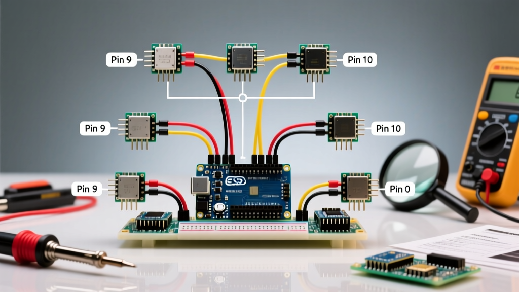
The widely used Arduino Servo Library relies on the microcontroller's internal 16-bit hardware timers to generate the precise 50Hz PWM pulses (1ms to 2ms high-time) that servos demand. On the Uno, the library hijacks Timer1. This hard-caps the software limit at 12 servos and has a major side effect: it disables analogWrite() functionality on pins 9 and 10.
3. The Power Trap (Current Draw)
This is where 90% of beginner projects fail. Servos are inductive loads that draw massive current spikes when starting, stopping, or operating under mechanical load (stall current).
- Arduino USB 5V Limit: Typically 500mA (USB 2.0) or 900mA (USB 3.0).
- Arduino Onboard 5V Regulator Limit: ~800mA to 1A maximum before thermal shutdown when powered via the barrel jack.
- TowerPro SG90 (9g Micro Servo): ~650mA stall current at 4.8V.
- TowerPro MG996R (Metal Gear): ~2.5A stall current at 6.0V.
Expert Warning: If you connect two MG996R servos to the Arduino's 5V pin and they move simultaneously under load, they will attempt to pull 5 Amps. This will instantly fry the Arduino's linear voltage regulator or trip your computer's USB overcurrent protection.
Microcontroller Servo Limits Matrix
The table below illustrates the theoretical versus practical limits for popular boards when using the standard Servo.h library and direct 5V pin power.
| Microcontroller Board | Total Digital Pins | Servo.h Max Limit | Safe Direct 5V Pin Limit | Best Use Case |
|---|---|---|---|---|
| Arduino Uno R3 / R4 | 14 | 12 | 1 to 2 (SG90 only) | Simple pan/tilt camera mounts |
| Arduino Nano | 14 | 12 | 1 (SG90 only) | Compact, low-torque prototypes |
| Arduino Mega 2560 | 54 | 48 | 1 to 2 (SG90 only) | Multi-axis robotic arms (with ext. power) |
| ESP32 DevKit V1 | ~25 (usable) | 16 (via LEDC) | 0 (Requires 3.3V to 5V level shifting) | IoT/Wi-Fi enabled robotics |
Scaling Up: The PCA9685 PWM Driver Solution
If your project requires more than two servos, or if you are using high-torque servos like the MG996R, you must decouple the signal generation from the power delivery. The industry-standard solution is the PCA9685 16-Channel 12-bit PWM/Servo Driver.
Why the PCA9685 is Essential
The PCA9685 communicates via I2C, meaning it only requires two pins (SDA and SCL) on your Arduino, regardless of how many servos you connect. The chip handles all the complex 50Hz timing calculations internally, freeing up your Arduino's hardware timers for other tasks like reading ultrasonic sensors or running PID loops.
Furthermore, the PCA9685 board features separate power terminals for the servo logic and the servo V+ (power). This allows you to supply high current directly to the servos without routing it through the Arduino.
Cost and Sourcing in 2026
- Generic PCA9685 Clones: $3.00 - $5.00 (Widely available on Amazon/AliExpress; perfectly fine for hobbyists).
- Adafruit 16-Channel PWM/Servo Driver (Product ID 815): ~$14.95 (Features superior terminal blocks and onboard voltage protection).
Step-by-Step: Wiring High-Torque Servos Safely
To control 6 MG996R servos for a hexapod robot leg assembly, follow this exact wiring protocol to prevent brownouts and jitter.
- Provide Dedicated Power: Use an external 5V or 6V power supply. For high-current setups, an LM2596 Buck Converter ($2 - $4) stepped down from a 12V LiPo battery or wall adapter is ideal. Set the multimeter to verify exactly 5.5V output before connecting.
- Add Bulk Capacitance: Solder or screw a 1000µF 10V (or 16V) electrolytic capacitor directly across the V+ and GND screw terminals on the PCA9685 board. This acts as a local energy reservoir to absorb transient current spikes when multiple servos start moving simultaneously.
- Wire the I2C Bus: Connect the PCA9685 SDA to Arduino A4, and SCL to Arduino A5. Connect the PCA9685 GND to the Arduino GND. Do not connect the V+ from the external supply to the Arduino 5V pin.
- Connect the Servos: Plug the servos into the PCA9685 output pins (0 through 15). Ensure the brown/black wire (GND) is on the bottom, red (V+) in the middle, and orange/yellow (Signal) on the top.
Software Implementation
Instead of the standard Servo.h library, install the Adafruit PWM Servo Driver Library via the Arduino Library Manager. This library allows you to set specific pulse widths (e.g., pwm.setPWM(0, 0, 350)) for smooth, jitter-free motion.
Troubleshooting Common Servo Failures
Even with the right hardware, beginners frequently encounter these edge cases:
Servo Jitter or Twitching
Cause: I2C bus noise or inadequate grounding.
Fix: Ensure the Arduino GND and the external power supply GND are tied together. If using long I2C wires (over 30cm), add 4.7kΩ pull-up resistors to the SDA and SCL lines.
Arduino Randomly Resetting
Cause: Voltage back-feeding or ground loops causing the Arduino's 5V rail to dip below 4.5V.
Fix: Check your wire gauge. Signal wires can be 22 AWG, but the main power rails feeding the PCA9685 V+ terminal must be at least 18 AWG or 16 AWG silicone wire to prevent voltage drop under load.
Servos Moving to 0 Degrees on Boot
Cause: The PCA9685 outputs are in an undefined state before the Arduino initializes the I2C bus and sends the first commands.
Fix: Wire the PCA9685 OE (Output Enable) pin to an Arduino digital pin. Set the Arduino pin HIGH in your setup() function to disable outputs during boot, then pull it LOW once your initial servo positions are written.
Final Verdict
If you are strictly using the Arduino's onboard pins and 5V regulator, you can safely control one, maybe two, 9-gram micro servos. If your project demands more than two servos, or requires high-torque metal-gear models, you must use an external BEC or buck converter paired with a PCA9685 I2C driver board. This combination effectively removes the Arduino's hardware limits, allowing you to chain up to 62 PCA9685 boards and control a staggering 992 servos from a single Arduino Uno.