
The PWM Bottleneck: Why 6 Pins Are Rarely Enough
When configuring PWM for Arduino projects, makers quickly hit a hardware wall. The classic ATmega328P-based boards (Uno, Nano) only offer six hardware Pulse Width Modulation pins. If you are building a hexapod robot requiring 18 servos, or an architectural lighting rig with dozens of dimmable LEDs, native pins fall drastically short. While software-based PWM (bit-banging) exists, it consumes precious CPU cycles and introduces severe jitter, rendering it useless for precision motor control or high-frequency LED dimming.
In this component comparison, we evaluate the three primary methods for generating and expanding PWM signals in the Arduino ecosystem: Native Microcontroller PWM (AVR and ESP32), the NXP PCA9685 I2C driver, and the Texas Instruments TLC5940 constant-current sink. We will dissect resolution limits, bus protocols, failure modes, and exact pricing to help you choose the right architecture for your next build.
Contender 1: Native Microcontroller PWM (AVR vs. ESP32)
Before adding external shields, it is critical to understand what your microcontroller provides natively. The implementation of hardware PWM varies wildly depending on whether you are using a classic 8-bit AVR or a modern 32-bit ESP32.
The ATmega328P (Uno/Nano) Limitations
The ATmega328P generates PWM using three internal timers (Timer0, Timer1, and Timer2). By default, the analogWrite() function outputs an 8-bit resolution (0-255) at approximately 490 Hz on most pins. Pins 5 and 6 operate at 980 Hz. While sufficient for basic DC motor speed control, this 8-bit resolution results in visible stepping when dimming LEDs at low brightness levels.
Critical Warning: Timer0 controls pins 5 and 6, but it also handles themillis()anddelay()functions. If you manually alter the Timer0 prescaler to achieve a 31 kHz PWM frequency for audio applications, you will completely break Arduino's internal timing functions.
The ESP32-S3 Advantage
If your project allows for the Arduino IDE but requires more native power, the ESP32-S3 is the 2026 standard. It features a dedicated LED Control (LEDC) peripheral boasting up to 14 independent PWM channels with 14-bit resolution (16,384 steps) and configurable frequencies up to 40 MHz. For many mid-scale projects, the ESP32-S3 eliminates the need for external drivers entirely.
Contender 2: PCA9685 16-Channel I2C PWM Driver
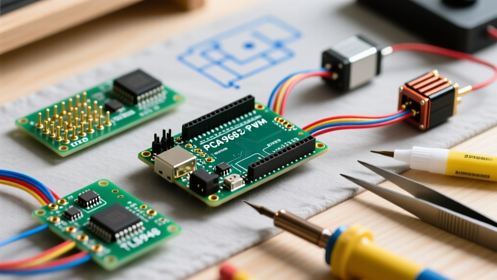
When native channels are exhausted, the NXP PCA9685 is the undisputed industry standard for servo and general-purpose PWM expansion. Communicating over the I2C bus, this chip offloads all pulse generation from the microcontroller.
Technical Specifications and Power Isolation
- Channels: 16 independent outputs
- Resolution: 12-bit (4096 steps per channel)
- Frequency: Programmable from 40 Hz to 1000 Hz
- Interface: I2C (up to 400 kHz Fast Mode)
A major architectural benefit of the PCA9685 is the physical separation of logic power (VCC) and servo/LED power (V+). On popular breakout boards (like the Adafruit 16-Channel PWM/Servo Shield, retailing around $19.95, or generic clones for $3.50), VCC is tied to the Arduino's 5V line for I2C logic, while V+ is routed through large screw terminals. This allows you to power high-torque servos directly from a 6V battery pack without back-feeding voltage into your microcontroller and frying the voltage regulator.
I2C Addressing and Bus Capacitance
The PCA9685 features six address selection jumpers (A0-A5), allowing up to 62 modules to share a single I2C bus (addresses 0x40 to 0x7F). However, chaining multiple modules introduces bus capacitance. If the total capacitance exceeds 400 pF, the I2C signal edges degrade, leading to missed packets and erratic servo twitching. In dense setups, you must drop the I2C clock speed to 100 kHz or add external 4.7kΩ pull-up resistors to the SDA and SCL lines.
Contender 3: TLC5940 16-Channel Constant-Current Sink
While the PCA9685 is ideal for servos, it is a voltage-source driver. For high-power LED matrices, architectural lighting, or RGB strips, the Texas Instruments TLC5940 is the superior choice. Unlike standard PWM drivers, the TLC5940 acts as a constant-current sink, ensuring uniform brightness across all LEDs regardless of minor forward voltage variations.
The IREF Resistor and Current Limiting
The TLC5940 does not require individual current-limiting resistors for every LED. Instead, you place a single reference resistor (R_IREF) between the IREF pin and ground. The chip uses this to set the maximum current sink for all 16 channels. Using the formula I_max = (1.24V / R_IREF) * 31.5, a 2.0 kΩ resistor yields a safe 19.5 mA per channel, perfect for standard 5mm through-hole LEDs. For high-power 1W or 3W star LEDs, you pair the TLC5940 with external MOSFET driver circuits.
Serial Protocol Complexity
The trade-off for the TLC5940's pristine LED dimming is protocol complexity. It does not use I2C. It requires a serial data line (SIN), a serial clock (SCLK), and three distinct timing signals: XLAT (latch), BLANK (reset), and GSCLK (grayscale clock). Generating the GSCLK requires a dedicated hardware timer on your Arduino, meaning you cannot easily use the TLC5940 alongside libraries that hijack Timer1 or Timer2 (like the standard Servo library).
Head-to-Head Comparison Matrix
| Feature | Native AVR (Uno) | Native ESP32-S3 | PCA9685 (I2C) | TLC5940 (Serial) |
|---|---|---|---|---|
| Max Channels | 6 | 14 | 16 (Chainable to 992) | 16 (Chainable via Daisy Chain) |
| Resolution | 8-bit (256) | 14-bit (16,384) | 12-bit (4096) | 12-bit (4096) |
| Output Type | Voltage Source | Voltage Source | Voltage Source (Totem-pole) | Constant-Current Sink |
| Best Application | Simple DC Motors | Complex Robotics | Servos, Relays, Strips | High-Power LED Matrices |
| Avg. Cost (2026) | $0 (Integrated) | $0 (Integrated) | $3.50 (Clone) / $19.95 (Name) | $4.00 - $8.00 (Breakout) |
| CPU Overhead | Low (Hardware Timer) | Low (LEDC Peripheral) | Zero (I2C updates only) | High (Requires GSCLK interrupts) |
Real-World Failure Modes and Troubleshooting
Theoretical specifications rarely tell the whole story. Based on extensive field testing in industrial and hobbyist environments, here are the most common edge cases and how to resolve them.
1. The PCA9685 'Midnight Twitch'
The Symptom: Servos connected to a PCA9685 randomly jump to 0 degrees or 180 degrees when a high-current load (like a relay or DC motor) switches on nearby.
The Fix: This is almost always caused by voltage sag on the V+ rail or I2C bus noise. The PCA9685 resets to its default state if the I2C bus drops below logic thresholds. Always use a dedicated, high-current BEC (Battery Eliminator Circuit) for the V+ terminal, and keep I2C traces under 30 cm. If routing over longer distances, use an I2C bus extender like the PCA9600.
2. TLC5940 Thermal Throttling
The Symptom: The TLC5940 chip becomes too hot to touch, and LEDs begin to flicker or dim unexpectedly after 10 minutes of operation.
The Fix: The TLC5940 dissipates excess voltage as heat. If you are driving blue LEDs (Vf ≈ 3.2V) from a 12V supply, the chip must burn off 8.8V per channel. At 20mA, that is 176mW of heat per channel. Multiplying this by 16 channels results in nearly 3 watts of heat on a tiny SMD package. Always match your power supply voltage as closely as possible to the LED forward voltage plus a 1.5V headroom, or attach a custom heatsink to the IC.
3. Native PWM Audio Whine
The Symptom: Using native Arduino PWM to drive a piezo buzzer or an audio amplifier results in a high-pitched, audible whine.
The Fix: Human hearing caps out around 20 kHz. The default 490 Hz PWM frequency falls squarely in the most sensitive range of human hearing. You must reconfigure the microcontroller's timer prescalers to push the PWM frequency to at least 31.25 kHz (ultrasonic). On the ATmega328P, this requires direct register manipulation of the TCCR registers, which, as noted earlier, will break standard Arduino timing functions.
Final Verdict: Which Should You Choose?
There is no universal 'best' PWM for Arduino; the correct choice depends entirely on your load type.
- Choose Native ESP32-S3 PWM if you are building a robot with up to 14 servos or motors and want to minimize BOM (Bill of Materials) costs and wiring complexity.
- Choose the PCA9685 if you are locked into the ATmega328P ecosystem, need to drive more than 6 servos, or require complete electrical isolation between your logic circuits and high-current motor power supplies.
- Choose the TLC5940 exclusively for high-density LED projects, POV (Persistence of Vision) displays, and RGB matrices where color uniformity and constant-current regulation are non-negotiable.
By matching the driver architecture to the physical requirements of your peripherals, you eliminate jitter, prevent thermal failures, and ensure your project operates reliably in the real world.