
The Reality of DC Motors for Arduino in the Field
If you have ever followed a beginner robotics tutorial, you are likely familiar with the yellow TT gearmotor. While it costs about $1.50 and is excellent for learning basic H-bridge logic on a breadboard, it is entirely unsuited for real-world applications. When tasked with pulling a 5kg payload across uneven greenhouse terrain or navigating warehouse floors, the plastic gears strip, the shafts bend, and the voltage sags brownout the microcontroller.
As we move through 2026, the hobbyist robotics landscape has matured. Building a reliable autonomous rover, an automated solar tracker, or a motorized camera dolly requires treating DC motors for Arduino not as simple toys, but as high-current inductive loads that demand rigorous electrical engineering. This guide bypasses the basics and dives straight into the physics, component selection, and wiring architectures required to build a robust 15kg payload autonomous rover.
⚠️ Critical Engineering Rule: Never power DC motors directly from the Arduino's 5V or 3.3V pins. Microcontroller GPIO pins can only source 20mA to 40mA. A standard hobby motor requires 500mA to 15,000mA. Attempting to drive a motor directly will instantly destroy the ATmega328P or ESP32 silicon.Sizing DC Motors for Arduino: A 15kg Rover Case Study
Selecting the right motor requires balancing voltage, stall current, gear ratio, and physical torque. For a 15kg (33 lbs) differential-drive rover operating on mixed terrain, we need high starting torque to overcome static friction and inertia. Below is a comparison of three common motor tiers used in Arduino projects today.
| Motor Model | Gear Ratio | No-Load RPM | Stall Current | Torque (kg-cm) | 2026 Avg. Price | Best Application |
|---|---|---|---|---|---|---|
| TT Gearmotor (Yellow) | 1:48 | 200 RPM | 800mA | 0.8 | $1.50 | Desktop line-followers |
| Pololu 25D (30:1) | 30:1 | 330 RPM | 1.5A | 4.5 | $24.00 | Indoor service robots (<5kg) |
| IG5208B Planetary | 19:1 | 315 RPM | 15.0A | 45.0 | $58.00 | Heavy outdoor rovers (15kg+) |
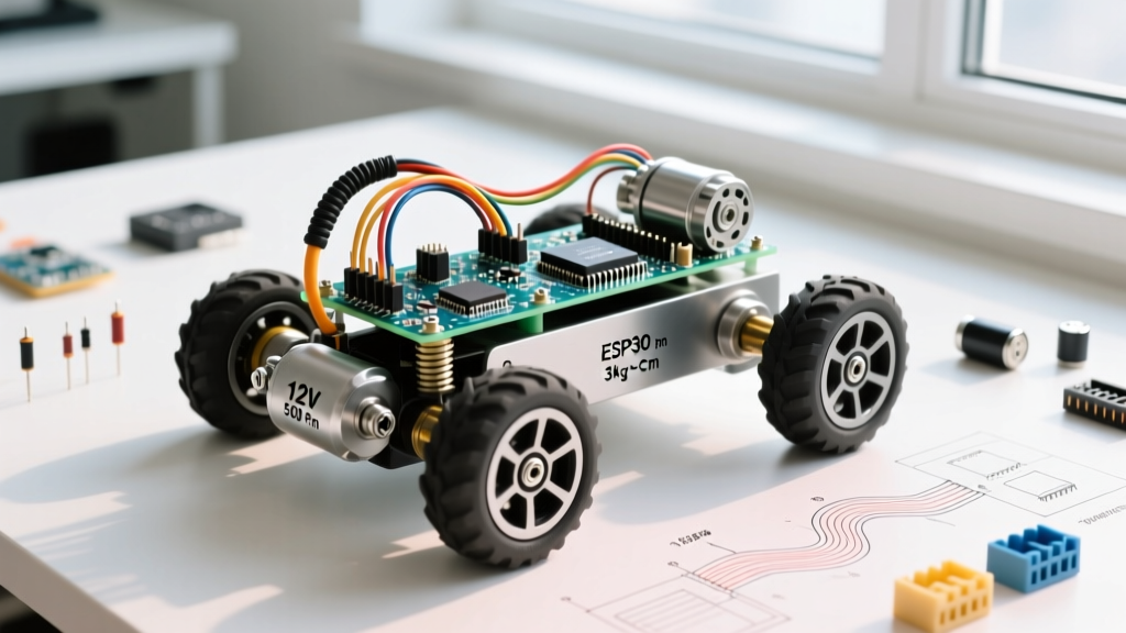
For our 15kg greenhouse rover, the IG5208B 12V Planetary Gearmotor is the only viable choice. Its metal planetary gearbox handles high shock loads without stripping, and the 45 kg-cm torque ensures the rover can climb 15-degree inclines without stalling.
Calculating Stall Current and Battery C-Ratings
Amateurs size batteries based on runtime; professionals size them based on stall current. When a motor starts from a dead stop, or hits an obstacle, it draws its maximum stall current. If you are using two IG5208B motors, your system must handle a combined 30A spike.
According to Battery University's guidelines on C-rates, a battery's discharge capability is determined by its C-rating. To safely supply 30A without severe voltage sag (which resets the Arduino), we use a 3S LiPo battery (11.1V nominal). A 2200mAh 3S LiPo with a 40C rating can deliver a continuous 88A (2.2A x 40). This provides a massive 2.9x safety margin over our 30A stall requirement, ensuring the voltage never drops below the 9V threshold required by the rover's onboard DC-DC converters.
Motor Driver Selection: Moving Past the L298N
The L298N motor driver is a relic of bipolar junction transistor (BJT) technology. It suffers from a massive internal voltage drop of 2V to 3V, which is dissipated as pure heat. In a 12V system, losing 2.5V across the driver means you are wasting over 20% of your battery capacity before the motor even spins.
- TB6612FNG (For Pololu 25D): Uses MOSFET technology with a voltage drop of only 0.5V. Handles 1.2A continuous and 3.2A peak per channel. Ideal for mid-tier indoor robots. (~$6.00)
- BTS7960 (For IG5208B): A high-power half-bridge driver based on Infineon ICs. Capable of handling 43A continuous current. It features built-in logic-level optoisolation and over-temperature shutdown. Essential for heavy-duty 12V-24V applications. (~$14.00 per module)
As detailed in SparkFun's motor driver guide, MOSFET-based drivers like the BTS7960 allow for highly efficient Pulse Width Modulation (PWM) speed control, generating significantly less heat and requiring fewer bulky heatsinks than legacy BJT bridges.
Real-World Wiring and Failure Prevention
Inductive kickback is the silent killer of Arduino rovers. When the PWM signal switches off, the magnetic field in the motor coil collapses, generating a massive reverse voltage spike (Back-EMF) that can easily exceed 100V. This spike will arc across contacts, destroy MOSFETs, and inject noise into your microcontroller's logic lines.
Step-by-Step Protection Architecture
- Flyback Diodes: Solder Schottky diodes (1N5819) directly across the motor terminals (cathode to positive, anode to negative). Schottky diodes are mandatory here because their fast switching speed (<50ns) clamps the voltage spike before it reaches the driver IC. Standard 1N4007 diodes are too slow.
- Star Grounding: Never daisy-chain your grounds. Connect the battery negative, the BTS7960 power ground, the motor ground, and the Arduino GND to a single, centralized brass bus bar. This prevents high motor currents from flowing through the Arduino's delicate ground traces.
- Logic Isolation: Use a dedicated 5V UBEC (Universal Battery Eliminator Circuit) rated for 3A to power the Arduino. Do not use the linear voltage regulator on the Arduino's barrel jack, as it will overheat and shut down when powering sensors and Wi-Fi modules simultaneously.
"If your Arduino randomly resets every time the motors change direction, you have a ground loop or a Back-EMF issue. Adding a 1000µF low-ESR electrolytic capacitor across the main battery terminals at the distribution board will absorb transient voltage dips during sudden motor reversals."
Software Tuning: Eliminating PWM Acoustic Whine
By default, Arduino's analogWrite() function operates at roughly 490Hz on most pins. When applied to high-torque DC motors, this low frequency causes the motor windings and chassis to vibrate audibly, creating an annoying, high-pitched acoustic whine. Furthermore, low-frequency PWM can cause cogging (jerky movement) at low speeds.
To fix this, we manipulate the ATmega328P hardware timers to increase the PWM frequency to the ultrasonic range (above human hearing, typically 20kHz+).
// Set Timer 1 (Pins 9 and 10 on Uno/Nano) to 20kHz Phase Correct PWM
void setup() {
  // Clear Timer 1 control registers
  TCCR1A = 0;
  TCCR1B = 0;

  // Set to Phase Correct PWM, Mode 1
  TCCR1A |= (1 << WGM11);

  // Set prescaler to 8 (16MHz / 8 / 255 / 2 = ~3.9kHz)
  // For 20kHz, use Mode 14 (Fast PWM) with ICR1 = 99
  TCCR1B |= (1 << WGM13) | (1 << WGM12) | (1 << CS11);
  ICR1 = 99; // TOP value for 20kHz at 8 prescaler

  // Enable PWM on Pin 9 and 10
  TCCR1A |= (1 << COM1A1) | (1 << COM1B1);

  pinMode(9, OUTPUT);
  pinMode(10, OUTPUT);
}

void loop() {
  // Use values from 0 to 99 instead of 0 to 255
  analogWrite(9, 50); // 50% duty cycle, silent operation
  delay(2000);
}
For comprehensive details on microcontroller hardware timers and safe inductive load handling, refer to the official Arduino documentation on motors.
FAQ: Troubleshooting Common Motor Issues
Why is my rover pulling to one side when driving straight?
Manufacturing tolerances in DC motors mean two identical motors will rarely spin at the exact same RPM under identical PWM signals. To correct this, implement a closed-loop PID controller using wheel encoders (like the Pololu magnetic encoders). The Arduino reads the encoder ticks and dynamically adjusts the PWM duty cycle to the slower motor to maintain a straight heading.
Can I use a relay module instead of a motor driver?
Only for binary on/off applications, like an automated window blind or a simple conveyor belt. Relays cannot perform PWM speed control, and reversing a DC motor with relays requires a complex DPDT wiring scheme. Furthermore, mechanical relays will suffer from severe contact arcing and weld shut if subjected to the 15A stall currents of heavy-duty motors. Always use solid-state MOSFET drivers for motor control.
My BTS7960 driver gets extremely hot at low speeds. Is this normal?
If you are using low-frequency PWM (490Hz), the MOSFETs spend a significant amount of time in the linear (transition) region, where they act as resistors and generate massive heat. Upgrading your PWM frequency to 20kHz, as shown in the code block above, forces the MOSFETs to switch fully on or fully off much faster, drastically reducing thermal output and eliminating the need for active cooling fans.