
Understanding Arduino Photo Sensor Technologies
When integrating an arduino photo sensor into a microcontroller project, hobbyists and engineers alike often default to the most basic component available without considering the environmental edge cases that can derail a deployment. Light sensing is not merely about detecting 'on' or 'off' states; it requires an understanding of spectral response, ADC (Analog-to-Digital Converter) resolution, and ambient noise rejection. Whether you are building an automated solar tracker, a smart streetlamp prototype, or a precision indoor lux meter, selecting the correct sensor topology and implementing robust signal conditioning is critical.
In this comprehensive integration tutorial, we will dissect the three primary light-sensing architectures available in the 2026 maker market: analog Cadmium Sulfide (CdS) photoresistors, analog phototransistors, and digital I2C luminosity ICs. We will provide exact wiring schematics, voltage divider mathematics, and advanced C++ code designed to defeat 50Hz/60Hz mains lighting flicker.
2026 Component Matrix: LDR vs. Phototransistor vs. Digital IC
Before wiring your circuit, you must select the appropriate sensor for your specific environmental constraints. The table below compares the three most common sensors used in Arduino ecosystems today.
| Sensor Type | Model Example | Output | Spectral Peak | Avg. Price (2026) | Best Use Case |
|---|---|---|---|---|---|
| Photoresistor (CdS) | GL5528 | Analog (Resistance) | 540nm (Visible) | $0.12 | Basic day/night detection, low-speed tracking |
| Phototransistor | TEMT6000 | Analog (Current) | 570nm (Visible) | $2.15 | Fast response, pulse-width light detection |
| Digital I2C IC | TSL2591 | Digital (I2C Lux) | Broadband (IR+Vis) | $4.95 | Precision lux metering, botanical grow lights |
Analog Integration: Wiring the GL5528 Photoresistor
The GL5528 is the undisputed workhorse of basic Arduino photo sensor projects. It is a light-dependent resistor (LDR) whose resistance drops as incident light increases. In complete darkness, a typical GL5528 exhibits a resistance of roughly 1MΩ. Under bright indoor lighting (approx. 100 lux), it drops to around 8kΩ–10kΩ.
Because microcontrollers cannot measure resistance directly, we must convert this variable resistance into a variable voltage using a voltage divider circuit. According to fundamental circuit principles outlined in SparkFun's voltage divider guide, the output voltage ($V_{out}$) is determined by the ratio of the fixed resistor to the total resistance.
The Voltage Divider and Hardware Filtering
For a 5V Arduino Uno, pairing the GL5528 with a 10kΩ fixed pull-down resistor provides the widest usable voltage swing across typical indoor and outdoor lighting conditions. However, raw analog readings from an LDR are notoriously noisy due to electromagnetic interference (EMI) and the physical composition of the CdS layer.
Hardware Pro-Tip: To stabilize your analog readings before they even reach the microcontroller, solder a 100nF (0.1µF) ceramic capacitor in parallel with your 10kΩ fixed resistor. This creates a passive low-pass filter with a cutoff frequency of roughly 159Hz, effectively shorting high-frequency EMI noise to ground while preserving the slow-changing DC signal of ambient light shifts.
Wiring Steps:
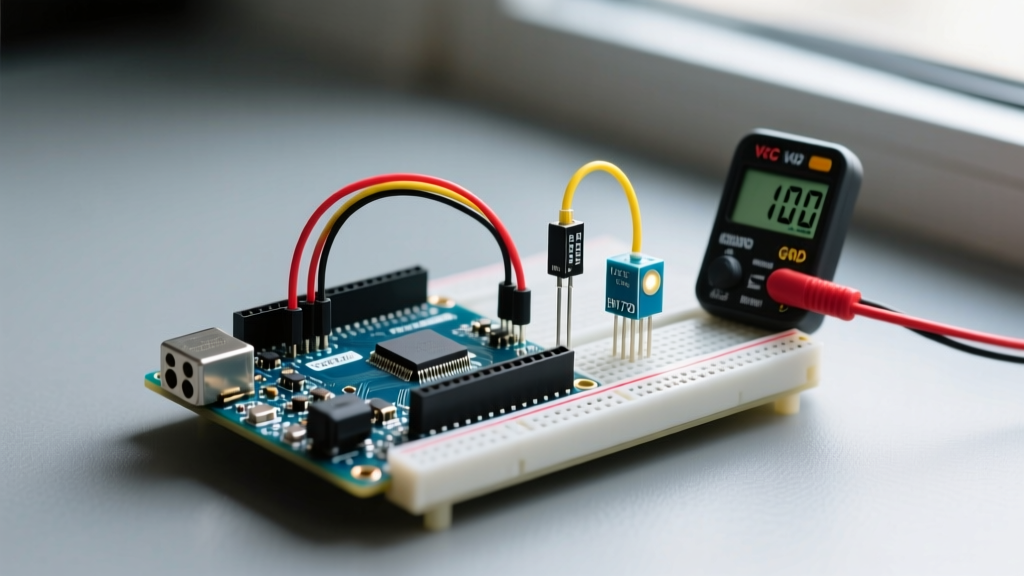
- Connect one leg of the GL5528 to the 5V pin on the Arduino.
- Connect the second leg of the GL5528 to Analog Pin A0.
- Connect a 10kΩ resistor between Analog Pin A0 and GND.
- Connect the 100nF capacitor in parallel with the 10kΩ resistor (between A0 and GND).
Software Calibration and Defeating Mains Flicker
A common failure mode in Arduino photo sensor deployments is erratic behavior triggered by artificial lighting. Incandescent bulbs and cheap, unregulated LED drivers flicker at twice the AC mains frequency (100Hz in 50Hz regions, 120Hz in 60Hz regions). If your Arduino samples the light level at the wrong microsecond, it will register this flicker as rapid changes in ambient light, causing relays to chatter or displays to flash.
To resolve this, we must implement a software moving-average filter combined with a hysteresis threshold. The official Arduino analogRead() documentation notes that standard 10-bit ADC conversions take approximately 100 microseconds. By oversampling and averaging, we smooth out the 100Hz/120Hz AC ripple.
// Arduino Photo Sensor Flicker-Rejection Code
const int ldrPin = A0;
const int relayPin = 8;

int lightReadings[20];
int readIndex = 0;
long total = 0;
int average = 0;

// Hysteresis thresholds to prevent relay chatter
const int turnOnThreshold = 450;  // Dark enough to turn on lights
const int turnOffThreshold = 550; // Bright enough to turn off lights

bool lightsOn = false;

void setup() {
  Serial.begin(115200);
  pinMode(relayPin, OUTPUT);
  digitalWrite(relayPin, LOW);

  // Initialize array
  for (int i = 0; i < 20; i++) {
    lightReadings[i] = 0;
  }
}

void loop() {
  // Subtract the last reading
  total = total - lightReadings[readIndex];

  // Read sensor and apply 5V mapping
  lightReadings[readIndex] = analogRead(ldrPin);

  // Add new reading to total
  total = total + lightReadings[readIndex];
  readIndex = (readIndex + 1) % 20;

  // Calculate the moving average
  average = total / 20;

  // Hysteresis logic
  if (!lightsOn && average < turnOnThreshold) {
    digitalWrite(relayPin, HIGH);
    lightsOn = true;
    Serial.println('Lights ON: Ambient dark detected.');
  }
  else if (lightsOn && average > turnOffThreshold) {
    digitalWrite(relayPin, LOW);
    lightsOn = false;
    Serial.println('Lights OFF: Ambient light restored.');
  }

  delay(50); // 50ms delay ensures we sample across multiple AC phases
}
Digital Alternatives: The TSL2591 I2C Breakout
While analog LDRs are cheap, they suffer from severe thermal drift and non-linear response curves. If your project requires actual lux measurements—for example, maintaining a precise 400-lux environment in a botanical grow tent or an office workspace—you must upgrade to a digital IC. The TSL2591 is a high-dynamic-range digital luminosity-to-frequency converter with an integrated IR blocking filter.
As detailed in Adafruit's TSL2591 learning guide, this sensor communicates via I2C and features an incredible 88dB dynamic range, allowing it to measure from deep shadow up to direct, blinding sunlight (up to 88,000 lux) without saturating the ADC. Wiring requires only four connections: VIN to 3.3V/5V, GND to GND, SCL to A5 (or dedicated SCL), and SDA to A4 (or dedicated SDA). Utilizing the Adafruit_TSL2591 library handles the complex internal gain and integration time calculations automatically, outputting a standardized lux float value.
Real-World Edge Cases and Troubleshooting
Even with perfect wiring and code, environmental factors can compromise your sensor integration. Keep these troubleshooting frameworks in mind during deployment:
- ESP32 ADC Non-Linearity: If you migrate this analog circuit from an Arduino Uno to an ESP32, be aware that the ESP32's 12-bit ADC is notoriously non-linear at the extremes (below 0.15V and above 3.1V). Always design your voltage divider so the expected operating range sits between 0.5V and 2.5V to ensure accurate mapping.
- Sensor Enclosure Cosine Correction: A bare LDR reads light from nearly 180 degrees. If you are building a directional solar tracker, you must 3D print a shroud or tube around the sensor to restrict its field of view. Without a physical collimator, diffuse skylight will wash out the directional data.
- Thermal Drift in CdS Cells: Cadmium Sulfide photoresistors change resistance based on temperature as well as light. If your sensor is mounted near a heat-generating component (like a voltage regulator or a high-power LED), the dark resistance will drop, tricking the microcontroller into thinking the environment is brighter than it actually is. Maintain a minimum 2-inch physical clearance from heat sources.
- IR Interference: Standard GL5528 LDRs are slightly sensitive to near-infrared light. If your project is deployed outdoors, the setting sun (which emits heavy IR) will cause the sensor to read 'brighter' than the actual visible lux level suggests. For outdoor solar tracking, add an IR-blocking (hot mirror) optical filter over the sensor housing.
By understanding the physical limitations of your chosen component and implementing both hardware filtering and software hysteresis, your Arduino photo sensor integration will transition from a fragile breadboard prototype to a robust, deployment-ready system.