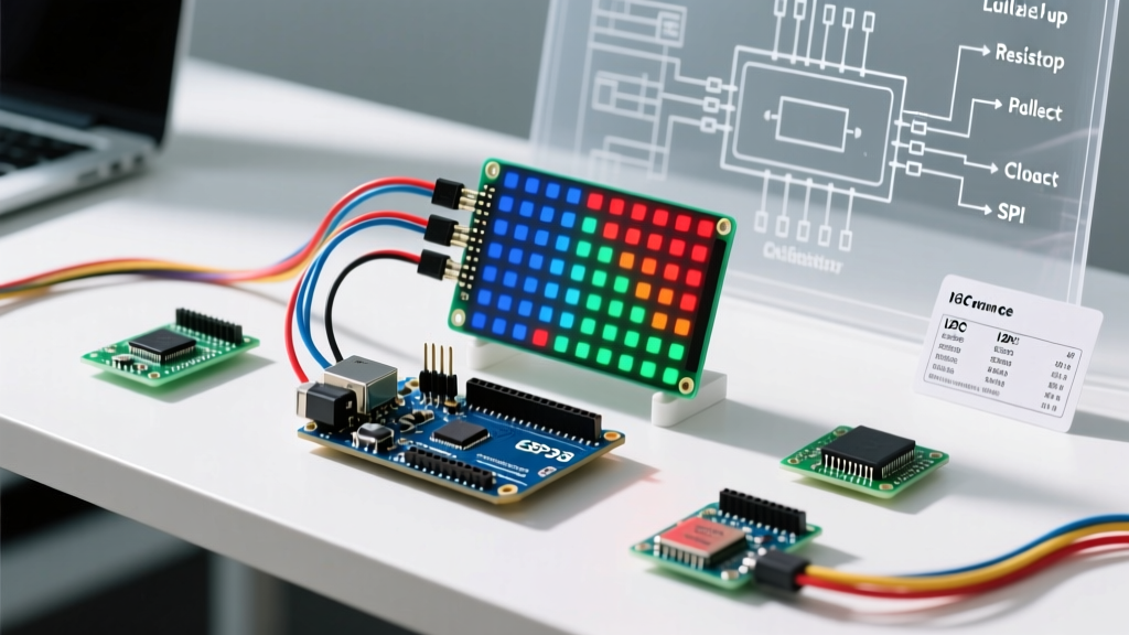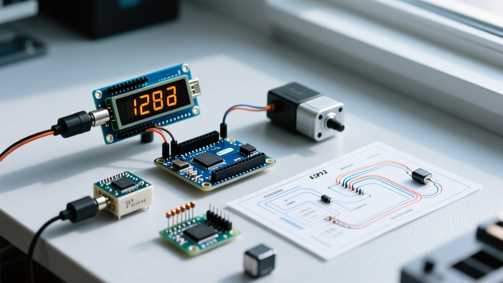

The Challenge of Mixed-Signal Multi-Peripheral Setups
Reading a standalone analog sensor is trivial. However, integrating an arduino liquid pressure sensor into a multi-peripheral ecosystem—where I2C displays, high-current relay modules, and inductive pump loads share the same microcontroller—introduces severe signal integrity challenges. As of 2026, while microcontrollers have become vastly more powerful, the fundamental physics of mixed-signal interference remain unchanged. When you trigger a 5V relay to activate a water pump, the resulting flyback voltage and ground bounce can inject massive amounts of noise into the microcontroller's Analog-to-Digital Converter (ADC), causing erratic pressure readings or complete system lockups.
This guide details the exact hardware architecture, filtering techniques, and software strategies required to build a robust, multi-peripheral liquid monitoring system using modern development boards.
Component Selection and Bill of Materials (BOM)
To build a reliable fluid monitoring node, we must move beyond legacy 8-bit architectures. The classic Arduino Uno R3's 10-bit ADC struggles with the millivolt-level fluctuations inherent in fluid dynamics. Instead, we utilize the Arduino Uno R4 Minima, which features a 12-bit (and optionally 14-bit) SAR ADC, providing 4x to 16x the resolution of older boards.
- Pressure Transducer: 0-1.2MPa (0-174 PSI) Stainless Steel Liquid Pressure Sensor (G1/4" thread, 5V excitation, 0.5V-4.5V analog output). Cost: $14 - $18.
- Microcontroller: Arduino Uno R4 Minima (RA4M1 ARM Cortex-M4). Cost: $20.
- Display: 0.96-inch SSD1306 I2C OLED (128x64). Cost: $8 - $12.
- Actuator: 5V Opto-isolated Relay Module (with built-in flyback diode). Cost: $4.
- Power Supply: LM2596 Buck Converter Module (set to 5.1V). Cost: $3.
Multi-Peripheral Wiring and Power Architecture
The most common point of failure in DIY fluid systems is powering high-current peripherals directly from the microcontroller's onboard 5V regulator. The onboard regulator cannot handle the transient current spikes of a relay coil alongside the steady draw of an OLED and sensor bridge.
Power Routing Matrix
| Component | Power Source | Ground | Signal / Data |
|---|---|---|---|
| Pressure Sensor (Red/Black) | External 5.1V Buck | Shared System GND | Analog Out (White) to A0 |
| SSD1306 OLED (VCC/GND) | Arduino R4 5V Pin | Arduino R4 GND | SDA to A4, SCL to A5 |
| Relay Module (VCC/GND) | External 5.1V Buck | Shared System GND | IN1 to Digital Pin 8 |
| Arduino Uno R4 (VIN/GND) | 12V Main Supply | Shared System GND | N/A |
Expert Tip: Always use a star-ground topology. Connect the ground from the external buck converter, the Arduino GND, and the sensor GND at a single physical terminal block. Never daisy-chain grounds on a breadboard, as the resistance of breadboard contacts will create ground loops that manifest as ADC noise.
Eliminating ADC Noise: Hardware and Software Tactics
Even with proper power routing, the digital clock edges of the I2C OLED and the electromagnetic interference (EMI) from the pump motor will corrupt your analog readings. According to DigiKey's comprehensive guide on RC filter design, implementing a simple passive low-pass filter is mandatory for stabilizing high-impedance analog signals.
Hardware: The RC Low-Pass Filter
Solder a 100Ω resistor in series with the sensor's analog output wire, followed by a 1µF ceramic capacitor to ground, placed as close to the Arduino's A0 pin as possible. This creates a low-pass filter with a cutoff frequency of approximately 1.59 kHz, effectively shorting high-frequency digital noise to ground while allowing the relatively slow-changing liquid pressure signal to pass.
Software: 12-Bit Resolution and Oversampling
The Arduino Uno R4 defaults to 12-bit resolution (0-4095). Because our sensor outputs 0.5V at 0 PSI and 4.5V at 174 PSI, we must map these specific thresholds. Furthermore, we implement a software oversampling technique, taking 16 rapid readings and averaging them to smooth out residual thermal noise.
const int pressurePin = A0;
const int relayPin = 8;

void setup() {
  analogReadResolution(12); // Force 12-bit on Uno R4
  pinMode(relayPin, OUTPUT);
  digitalWrite(relayPin, HIGH); // Relay modules are often active-LOW
  Serial.begin(115200);
}

float getStablePressurePSI() {
  long total = 0;
  for (int i = 0; i < 16; i++) {
    total += analogRead(pressurePin);
    delayMicroseconds(50); // Allow ADC sample-and-hold cap to settle
  }
  int avgRaw = total / 16;
  // Map 0.5V (409) to 4.5V (3686) -> 0 to 174 PSI
  float psi = map(avgRaw, 409, 3686, 0, 17400) / 100.0;
  return constrain(psi, 0.0, 174.0);
}
For advanced noise rejection, you can also bypass the internal voltage reference noise by feeding a clean 4.096V external reference into the AREF pin and adjusting your code using the Arduino analogReference() documentation as a guide.
Managing the I2C Bus in Fluid Environments
When integrating the SSD1306 OLED to display real-time PSI, you are adding capacitance to the I2C bus. In humid or wet environments, moisture ingress on the PCB can further increase parasitic capacitance, leading to I2C bus lockups. As detailed in Adafruit's OLED wiring and integration guide, ensuring proper pull-up resistor values is critical.
If your OLED module already has 10kΩ pull-up resistors on the SDA and SCL lines (common on cheap clones), and you add another sensor to the same bus, the parallel resistance drops, potentially causing signal degradation. For the Uno R4 operating at standard 100kHz I2C speeds, 4.7kΩ pull-ups to 3.3V or 5V are optimal. If the bus locks up when the relay switches, consider dropping to 2.2kΩ pull-ups to sharpen the rising edges of the I2C signals.
Real-World Fluid Dynamics: Water Hammer and Cavitation
Software and electronics are only half the battle. The physical installation of an arduino liquid pressure sensor introduces mechanical failure modes that will destroy your hardware if ignored.
The Water Hammer Effect
When your relay triggers a solenoid valve to close rapidly, the kinetic energy of the moving water column slams into the closed valve, creating a shockwave known as water hammer. This pressure spike can easily exceed 300 PSI for a fraction of a millisecond—far beyond the 174 PSI maximum rating of a 1.2MPa sensor. This will not only max out your ADC but can physically rupture the sensor's internal ceramic diaphragm.
- Solution 1 (Mechanical): Install a pneumatic water hammer arrester or a physical pressure snubber (a tiny brass fitting with a 0.5mm orifice) directly in front of the sensor port.
- Solution 2 (Software): Program the microcontroller to close the valve using PWM or a multi-stage actuation if using a motorized ball valve, rather than snapping a solenoid shut instantly.
Thread Sealing and Torque Limits
The G1/4" BSP threads on stainless steel transducers are tapered. Do not use PTFE (Teflon) tape, as shreds can break off and clog the sensor's 1mm pressure port. Instead, use a liquid PTFE pipe thread sealant. Furthermore, tighten the sensor using a wrench on the hex base only. Applying torque to the cylindrical body will twist the internal PCB, snapping the delicate gold bond wires connecting the strain gauge bridge to the amplifier IC.
Troubleshooting Common Integration Failures
Even with meticulous planning, multi-peripheral setups exhibit unique edge cases. Here is a diagnostic framework for the most common issues encountered in 2026 field deployments:
- Symptom: OLED display freezes when the relay clicks.
Diagnosis: Flyback voltage from the relay coil is resetting the Arduino or corrupting the I2C bus.
Fix: Verify the opto-isolator on the relay module is actually engaged (remove the VCC-JD jumper on standard modules and power the relay side with the external buck converter). - Symptom: Pressure reads 15 PSI when the system is fully depressurized (0 PSI).
Diagnosis: The 5V excitation voltage from the buck converter is sagging to 4.7V under load, or the sensor's internal offset is drifting.
Fix: Measure the sensor's Red wire voltage with a multimeter while the relay is active. If it drops below 4.9V, upgrade the buck converter's inductor or add a 470µF electrolytic capacitor across the sensor's power pins. - Symptom: Readings slowly climb over 24 hours despite no pressure change.
Diagnosis: Thermal drift. Stainless steel sensors exhibit a 0.2% F.S. (Full Scale) shift per 10°C change.
Fix: Mount the sensor away from the heat generated by the pump motor and the Arduino's voltage regulator.
By treating the arduino liquid pressure sensor not as an isolated component, but as part of a complex electromechanical system, you ensure long-term reliability and precision in your DIY fluid control projects.