
Beyond the Library: The Reality of LED Matrix Calibration
When most makers connect an Arduino LED matrix for the first time, they rely on plug-and-play libraries like MD_MAX72XX or Adafruit_NeoPixel. While these libraries get pixels on the screen, the out-of-the-box performance is rarely optimal. Un-calibrated matrices suffer from uneven brightness, severe color shifting at low PWM levels, and the dreaded 'ghosting' effect where faint afterimages trail across rows. In 2026, with high-density matrices becoming cheaper and more prevalent, understanding the electrical and mathematical calibration required for true visual accuracy is what separates amateur projects from professional-grade installations.
This guide dives deep into the hardware tuning, gamma correction mathematics, and timing adjustments required to calibrate the three most common Arduino LED matrix architectures: multiplexed monochrome (MAX7219), addressable RGB (WS2812B/NeoPixel), and Charlieplexed (IS31FL3731).
The Core Calibration Challenges in LED Matrices
Before writing code, we must identify the physical and perceptual bottlenecks inherent to LED matrices:
- Parasitic Ghosting: In multiplexed matrices, PCB trace capacitance holds residual charge when the MOSFET switches off, causing unselected LEDs to glow faintly.
- Perceptual Non-Linearity: Human vision does not perceive light linearly. A 50% PWM duty cycle appears roughly 73% as bright as 100%, ruining smooth fades.
- Forward Voltage ($V_f$) Discrepancies: In RGB matrices, red LEDs require less voltage than blue or green. As voltage drops across long chains, red dominates, shifting 'white' to a muddy pink.
- Beat Frequency Flicker: PWM frequencies that clash with camera shutter speeds or AC mains lighting create visible banding and strobing.
Monochrome Matrix Calibration (MAX7219 8x8)
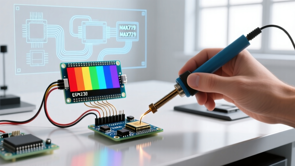
The MAX7219 is the workhorse of monochrome Arduino LED matrix projects. However, cheap clone boards often feature incorrect current-limiting resistors and suffer from SPI timing issues that cause row-shifting and ghosting.
Tuning the $R_{set}$ Resistor for Current Accuracy
The MAX7219 does not use a fixed current limit; it relies on an external resistor ($R_{set}$) connected between pin 18 (ISET) and VCC. According to the Analog Devices MAX7219 datasheet, the segment current is calculated as $I_{seg} = \frac{40V}{R_{set}}$.
Most mass-produced clone boards ship with a 10kΩ resistor, yielding a mere 4mA per segment. This makes the matrix dim and highly susceptible to ambient light washout. Conversely, using a 1kΩ resistor pushes 40mA, which will overheat the IC and cause thermal shutdown.
Expert Recommendation: Desolder the factory 10kΩ resistor and replace it with a 4.7kΩ surface-mount or through-hole resistor. This provides ~8.5mA per segment—the optimal sweet spot for high indoor visibility while keeping the IC temperature below 40°C.
Eliminating Ghosting via SPI Clock and Blanking Time
Ghosting on the MAX7219 is rarely a software bug; it is an electrical timing issue. When the SPI clock runs too fast over long jumper wires (e.g., 16MHz on a standard Arduino Uno), signal reflection causes the chip to misinterpret the 'no-op' commands during row transitions.
The Fix: In your Arduino setup, force the SPI clock divider down. If you are using the standard SPI library, insert SPI.setClockDivider(SPI_CLOCK_DIV4); to drop the clock to 4MHz. Furthermore, if you are writing a custom multiplexing ISR (Interrupt Service Routine) for larger matrices, you must insert a 2µs 'dead time' (blanking) where all rows are driven HIGH (off) before switching the column data. This allows the parasitic capacitance in the PCB traces to discharge.
RGB Matrix Color Accuracy (WS2812B / NeoPixel)
Addressable RGB matrices like the WS2812B (commonly branded as NeoPixels) bypass multiplexing but introduce severe color calibration challenges. As of early 2026, a standard 8x8 WS2812B matrix costs around $12–$15, making them ubiquitous, yet their color accuracy out of the box is notoriously poor.
Implementing Gamma Correction Lookup Tables (LUT)
To achieve smooth gradients and accurate dimming, you must apply gamma correction. The Adafruit NeoPixel UberGuide extensively documents that human eyes follow a power-law curve. To map a linear 0-255 input to a perceptually linear output, you must apply a gamma exponent of roughly 2.8.
Instead of calculating pow(input / 255.0, 2.8) * 255 on the fly—which consumes precious CPU cycles and causes animation stuttering on 8-bit AVR Arduinos—you must use a pre-calculated Lookup Table (LUT) stored in PROGMEM.
| Linear Input (0-255) | Gamma Corrected Output | Perceived Brightness |
|---|---|---|
| 0 | 0 | 0% |
| 32 | 2 | ~1% |
| 64 | 10 | ~4% |
| 127 | 55 | ~21% |
| 191 | 144 | ~56% |
| 255 | 255 | 100% |
White-Balance and Voltage Drop Compensation
WS2812B chips inherently run 'green-heavy' due to the higher luminous efficacy of the green InGaN die. If you send (255, 255, 255), the result will look distinctly mint-green. To calibrate for a true D65 daylight white point, you must restrict the green channel in your firmware. A standard calibration profile for generic WS2812B matrices is R: 255, G: 195, B: 235.
Furthermore, voltage drop across the matrix traces alters color. The red LED has a forward voltage ($V_f$) of ~2.0V, while blue and green require ~3.2V. By the time power reaches the 64th LED in a chain, the local voltage may drop to 4.1V. The blue and green dies will starve and dim, leaving only the red LED shining. To maintain color accuracy across the entire matrix, you must inject 5V power at both the top and bottom edges of the matrix, using 22 AWG silicone wire to minimize $I^2R$ losses.
Charlieplexed Matrices (IS31FL3731) PWM Tuning
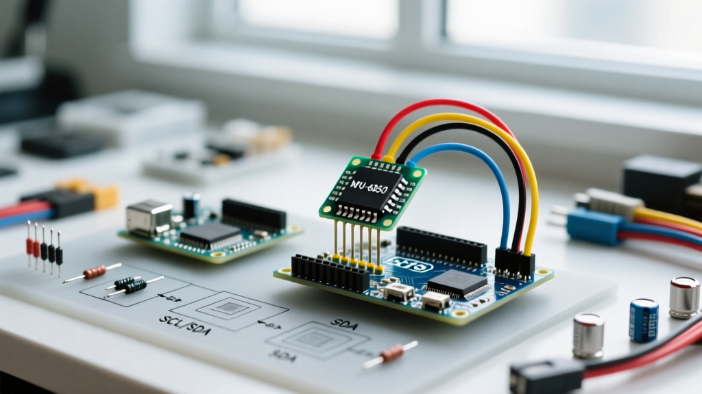
The IS31FL3731 drives 16x9 Charlieplexed matrices. Unlike the WS2812B, it uses a dedicated I2C PWM controller. The primary calibration task here is tuning the Global Current Control (GCC) register and the PWM frequency to avoid camera flicker.
By default, the IS31FL3731 runs its PWM at roughly 1.2kHz. If you record your Arduino LED matrix with a smartphone camera at 60fps, you will see rolling black bands. To fix this, access the Function Register (page 0x0B) and adjust the PWM frequency setting to a higher harmonic, or sync the refresh rate to your camera's shutter speed. Additionally, set the GCC register (0x01) to 0x80 (128) to cap the maximum current at 50%, preventing the tiny 0603 SMD LEDs from overheating and shifting their color temperature.
Hardware Calibration Toolkit
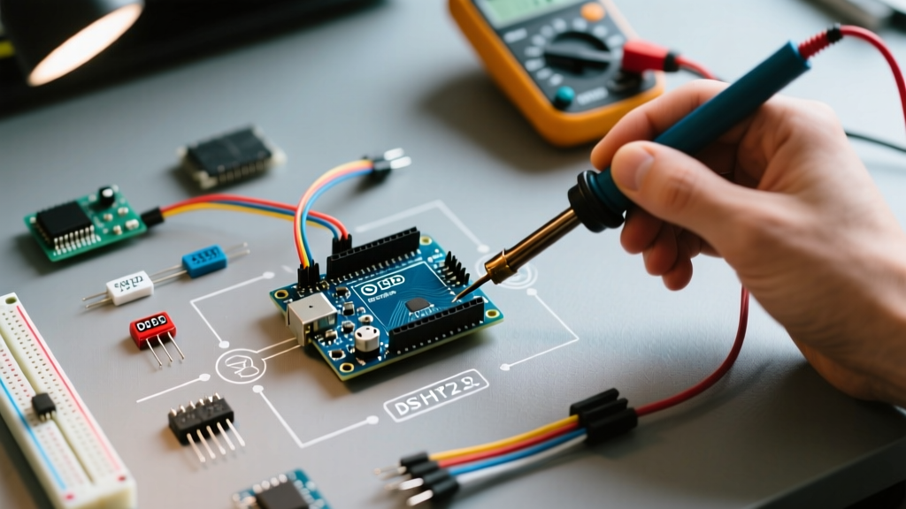
Software can only go so far. For professional installations, you need physical measurement tools to verify your matrix calibration.
- Digital Multimeter (True RMS): Essential for measuring the voltage drop across the VCC and GND rails at the furthest LED. Acceptable drop is < 0.2V.
- Lux Meter / Spectrometer: A basic lux meter verifies overall brightness uniformity. For color accuracy, a handheld spectrometer (like the Sekonic C-700, though expensive) or a calibrated smartphone app (like Spectral Pro) helps verify the CIE 1931 color coordinates of your white point.
- Oscilloscope (or Logic Analyzer): A $15 USB logic analyzer is sufficient to verify SPI clock polarity (CPOL/CPHA) and measure the exact blanking time between multiplexed row shifts to diagnose ghosting.
Troubleshooting Matrix: Symptoms and Fixes
| Symptom | Root Cause | Calibration Fix |
|---|---|---|
| Faint ghosting on adjacent rows | Parasitic trace capacitance / SPI signal reflection | Add 100pF bleeder capacitors; reduce SPI clock to 4MHz; add 2µs blanking dead-time. |
| White looks pink/muddy at the edges | Voltage drop starving Blue/Green dies | Inject 5V power at multiple points; use thicker gauge wire for VCC/GND. |
| Choppy, stepped fading at low brightness | Linear PWM mapping vs. human eye perception | Implement a 2.8 Gamma Correction LUT in PROGMEM. |
| Matrix flickers on smartphone cameras | PWM beat frequency mismatch | Adjust IS31FL3731 PWM frequency register; ensure power supply has low ripple. |
| Entire matrix is dim and lacks punch | Oversized $R_{set}$ resistor on MAX7219 | Replace 10kΩ $R_{set}$ resistor with a 4.7kΩ resistor. |
Final Thoughts on Matrix Accuracy
Calibrating an Arduino LED matrix is an exercise in bridging the gap between digital logic and analog physics. By taking the time to swap out current-limiting resistors, implement gamma correction lookup tables, and manage voltage distribution, you elevate your project from a blinking toy to a visually stunning, accurate display. Whether you are building a retro arcade cabinet or a modern interactive art piece, these calibration techniques ensure your matrix performs flawlessly in the real world.