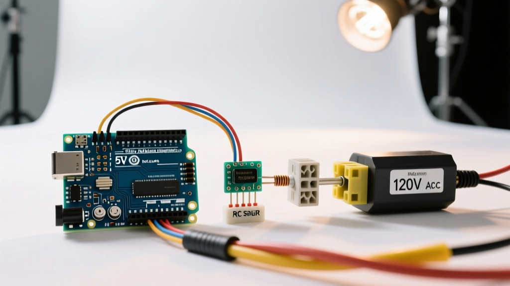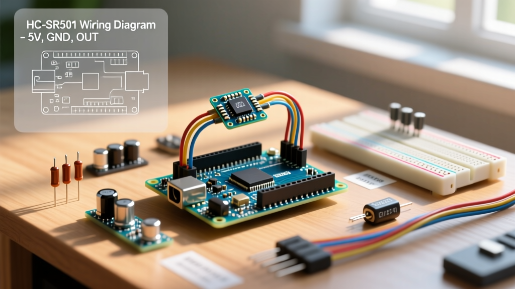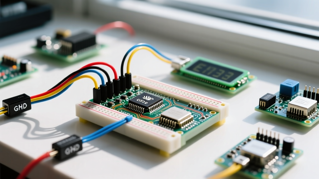

The Multi-Peripheral Challenge: Beyond the Basic Humidity Sensor for Arduino
Connecting a single sensor to a microcontroller is a rite of passage, but real-world environmental monitoring requires a multi-peripheral approach. When you integrate a high-accuracy humidity sensor for Arduino alongside an SSD1306 OLED display, a DS3231 Real-Time Clock (RTC), and an SD card logger, the simplicity of the I2C bus quickly unravels. Signal degradation, address collisions, and power budgeting become the primary points of failure.
In 2026, the maker and industrial IoT markets have largely moved past the legacy DHT11/DHT22 sensors for professional multi-device rigs. Instead, I2C-native silicon like the Sensirion SHT31-D and Bosch BME280 dominate. This guide details the electrical engineering realities of wiring, biasing, and coding a premium humidity sensor in a crowded multi-peripheral I2C environment.
Sensor Selection Matrix for Crowded I2C Buses
Choosing the right sensor dictates your bus topology. Legacy 1-Wire sensors require precise microsecond timing, which interrupts I2C transactions and causes OLED screen tearing. Native I2C sensors offload timing to the hardware TWI (Two-Wire Interface) peripheral.
| Model | Protocol | I2C Address Config | RH Accuracy | 2026 Avg Price | Multi-Device Suitability |
|---|---|---|---|---|---|
| DHT22 | 1-Wire | None (Fixed) | ±2% | $3.50 | Poor (Blocks bus/CPU) |
| SHT31-D | I2C | 2 Addresses (0x44, 0x45) | ±2% | $6.50 | Excellent (Fast, reliable) |
| BME280 | I2C / SPI | 2 Addresses (0x76, 0x77) | ±3% | $4.50 | Great (SPI bypasses I2C limits) |
For strict I2C multi-peripheral setups, the Sensirion SHT31-D is the optimal humidity sensor for Arduino. Its fully calibrated CMOSens technology ensures stable readings even when bus noise is present, and its dual-address capability allows for spatial differential humidity tracking.
I2C Physics: Bus Capacitance and Pull-Up Resistor Math
The most common failure in multi-peripheral I2C setups is ignoring bus capacitance. The I2C specification mandates a maximum bus capacitance of 400pF. Every breakout board, wire, and microcontroller pin adds parasitic capacitance. An SSD1306 OLED adds ~20pF, a DS3231 adds ~15pF, and the SHT31-D adds ~10pF. While the sensors themselves won't breach the 400pF limit, the physical wiring in a breadboard or unshielded ribbon cable easily will, resulting in rounded SDA/SCL waveforms and NACK (Not Acknowledged) errors.
The Pull-Up Resistor Collision
I2C lines are open-drain and require pull-up resistors. Most commercial breakout boards include 4.7kΩ or 10kΩ surface-mount pull-ups. When you wire three devices in parallel, their pull-up resistors are also in parallel.
The Parallel Resistor Trap:
If your OLED has 10kΩ, your RTC has 4.7kΩ, and your SHT31 has 10kΩ pull-ups, the net pull-up resistance drops to roughly 2.4kΩ. On a 5V bus, this sinks over 2mA. While within the 3mA I2C sink limit, it increases power consumption and can cause voltage sag on poorly regulated 3.3V lines.
Actionable Fix: Use an I2C scanner sketch to check signal integrity. If you experience intermittent drops, remove the pull-up resistors from two of the breakout boards (using a soldering iron to desolder the 0603 SMD resistor) and rely on a single, centralized 4.7kΩ pull-up pair on your main bus distribution board.
Hardware Wiring: Level Shifting and Decoupling
The SHT31-D and BME280 are strictly 3.3V logic devices. Connecting them directly to the 5V SDA/SCL pins of an Arduino Uno or Nano will degrade the sensor's internal ESD protection diodes over time, leading to permanent thermal drift.
Step-by-Step 5V to 3.3V Integration
- Power Distribution: Route the Arduino 5V pin to a dedicated 3.3V LDO voltage regulator (like the AMS1117-3.3) capable of supplying 800mA. Do not rely on the Arduino's onboard 3.3V pin, which is often limited to 50mA and shared with the USB-to-Serial chip.
- Logic Level Translation: Insert a BSS138 MOSFET-based bidirectional logic level shifter ($1.20) between the Arduino 5V I2C pins and the 3.3V sensor bus. This ensures clean 3.3V logic highs reach the SHT31-D without overvoltage stress.
- Decoupling Capacitors: The SHT31-D features an internal heater element used to burn off condensation. Activating this heater causes a sudden current spike of up to 30mA. Place a 100nF ceramic capacitor and a 10µF tantalum capacitor within 5mm of the sensor's VCC and GND pins to prevent local voltage brownouts that could reset the I2C state machine.
Firmware Strategy: Non-Blocking Multi-Device Polling
When reading a humidity sensor for Arduino alongside an OLED display, using blocking code like delay() is fatal to the user interface. The Arduino Wire library handles I2C transactions, but sensor measurement cycles take time (up to 15ms for high-repeatability SHT31 readings).
Instead of halting the CPU, implement a state-machine approach using millis(). Send the measurement command to the SHT31-D, update the OLED display, read the RTC, and then return to check if the humidity data is ready.
// Non-blocking SHT31-D trigger snippet
Wire.beginTransmission(0x44);
Wire.write(0x2C); // High repeatability MSB
Wire.write(0x06); // High repeatability LSB
Wire.endTransmission();
// CPU is now free to update OLED or read RTC
By decoupling the I2C 'send command' and 'read result' phases, you maintain a smooth 60Hz refresh rate on your TFT or OLED displays while gathering precision environmental data.
Troubleshooting Edge Cases in Complex Rigs
Multi-peripheral setups introduce unique failure modes that single-sensor tutorials never cover. Consult this diagnostic matrix when your I2C scanner fails to detect the humidity sensor.
| Symptom | Root Cause | Hardware / Firmware Fix |
|---|---|---|
| Sensor shows 100% RH and 80°C constantly | Internal heater stuck ON due to I2C bus corruption mid-transaction. | Implement a watchdog timer and send a soft-reset command (0x30 0xA2) on boot. |
| I2C Scanner shows 'ghost' addresses (e.g., 0x00 to 0x07) | SDA line floating or severe capacitive coupling from adjacent SPI clock lines. | Separate I2C and SPI traces by at least 2mm; ensure continuous ground plane. |
| Sensor drops off bus when OLED updates | OLED screen refresh draws 20mA spike, causing VCC sag below sensor's 2.15V minimum. | Add 47µF bulk capacitance to the main 3.3V rail; use star-ground topology. |
| NACK error only on the 2nd humidity sensor | Address collision; both SHT31-D sensors have the ADDR pin tied to GND (0x44). | Pull the ADDR pin of the second sensor to VCC to shift it to 0x45. |
Final Thoughts on Bus Architecture
Integrating a premium humidity sensor for Arduino into a multi-peripheral setup requires shifting your mindset from 'pin-to-pin wiring' to 'bus architecture.' By respecting the 400pF capacitance limit, mathematically managing pull-up resistors, and utilizing BSS138 level shifters, you guarantee robust, industrial-grade data acquisition. For deeper electrical specifications on I2C timing and capacitance tolerances, refer to the definitive NXP I2C-bus specification and user manual (UM10204).