
The Display Dilemma: Character vs. Graphic
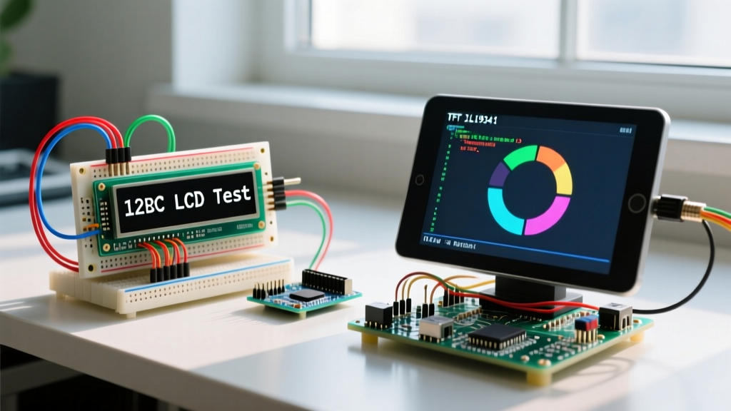
When developers search for Arduino code LCD examples, they typically encounter two vastly different ecosystems: the ubiquitous 16x2 character LCD and the vibrant TFT graphic displays like the ILI9341. Choosing between them is not merely a hardware decision; it fundamentally dictates your microcontroller's memory allocation, wiring complexity, and loop execution speed. As we navigate the component landscape in 2026, the price gap between basic character displays and entry-level TFTs has narrowed, but the software overhead remains drastically different.
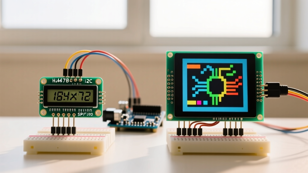
This comprehensive component comparison dissects the hardware architecture, library ecosystems, and real-world failure modes of the HD44780-based 16x2 I2C LCD versus the 2.4-inch ILI9341 SPI TFT. Whether you are building a low-power environmental monitor or a high-refresh-rate oscilloscope, understanding the underlying code requirements is critical for project success.
Hardware & Pinout Comparison Matrix
Before diving into the code, we must establish the hardware baselines. The table below contrasts the standard 16x2 I2C module (equipped with a PCF8574 backpack) against a standard 2.4" ILI9341 SPI TFT module.
| Feature | 16x2 I2C LCD (HD44780 + PCF8574) | 2.4" TFT LCD (ILI9341 SPI) |
|---|---|---|
| Resolution | 16 columns x 2 rows (Character) | 320 x 240 pixels (Graphic) |
| Communication | I2C (SDA, SCL) | SPI (MOSI, MISO, SCK, CS, DC) |
| Operating Voltage | 5V (Logic & Backlight) | 3.3V Logic (5V tolerant on some VCC pins) |
| Typical 2026 Price | $3.50 - $5.00 USD | $13.00 - $17.00 USD |
| Refresh Rate | ~10 Hz (Visible text updates) | Up to 60+ FPS (Hardware SPI) |
| Controller Chip | HD44780 / ST7066U | ILI9341 |
Deep Dive: 16x2 I2C Character LCD
Code Implementation & The PCF8574 Expander
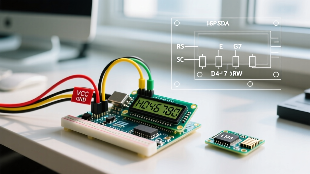
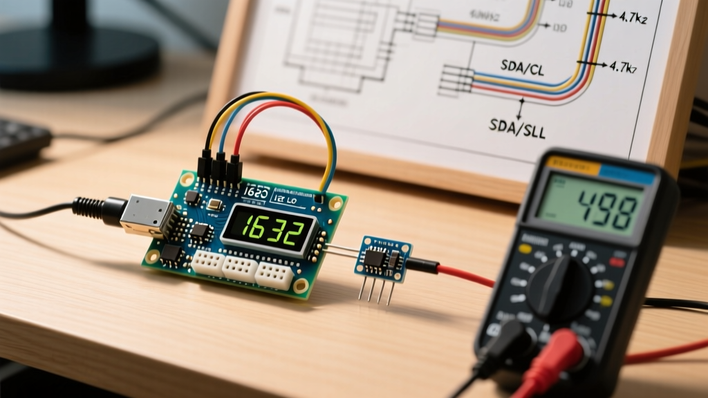
The 16x2 LCD natively requires 6 digital pins in 4-bit mode. To save GPIO pins, manufacturers solder a PCF8574 I/O expander to the back, converting the parallel interface to I2C. This reduces the wiring to just four pins (VCC, GND, SDA, SCL) but introduces a software translation layer. The industry-standard library for this is LiquidCrystal_I2C by Frank de Brabander.
#include <Wire.h>
#include <LiquidCrystal_I2C.h>

// Initialize with I2C address 0x27, 16 columns, 2 rows
LiquidCrystal_I2C lcd(0x27, 16, 2);

void setup() {
  lcd.init();
  lcd.backlight();
  lcd.setCursor(0, 0);
  lcd.print("ElectricalFlux");
  lcd.setCursor(0, 1);
  lcd.print("16x2 I2C Test");
}

void loop() {
  // Static display, no loop processing needed
}
Failure Modes & Edge Cases
- The I2C Address Guessing Game: The most common point of failure for beginners is the hardcoded I2C address. While 0x27 is standard for PCF8574AT chips, modules using the PCF8574T chip default to 0x3F. If your screen remains blank with the backlight on, run an I2C scanner sketch. You can reference the comprehensive Adafruit I2C Address List to verify chip mappings.
- Contrast Potentiometer Misalignment: Unlike TFTs, character LCDs require a physical contrast adjustment. If the blue I2C backpack has a blue trim-pot, you must turn it with a small Phillips screwdriver until the pixel grid is faintly visible before uploading code.
- Blocking I2C Bus: The
Wire.hlibrary uses a 100kHz default clock. Writing a full 32-character screen takes roughly 3.5 milliseconds. While fast, doing this inside a tightloop()without delays can cause I2C bus contention if you are also polling high-speed sensors like an MPU6050.
Deep Dive: 2.4" TFT SPI LCD (ILI9341)
Code Implementation & The GFX Ecosystem
The ILI9341 is a graphic powerhouse capable of rendering 65,536 colors (16-bit RGB565). Writing Arduino code LCD routines for this display requires a robust graphics engine. The Adafruit GFX library provides the drawing primitives (pixels, lines, rectangles, and fonts), while the hardware-specific Adafruit_ILI9341 library handles the SPI communication.
#include "SPI.h"
#include "Adafruit_GFX.h"
#include "Adafruit_ILI9341.h"

// Pin definitions for Arduino Uno / ATmega328P
#define TFT_CS 10
#define TFT_DC 9
#define TFT_RST 8

Adafruit_ILI9341 tft = Adafruit_ILI9341(TFT_CS, TFT_DC, TFT_RST);

void setup() {
  tft.begin(40000000); // Attempt 40MHz SPI clock
  tft.setRotation(3);  // Landscape mode
  tft.fillScreen(ILI9341_BLACK);

  tft.setTextColor(ILI9341_YELLOW);
  tft.setTextSize(3);
  tft.setCursor(20, 40);
  tft.print("TFT ILI9341");
}

void loop() {
  // Graphic rendering logic here
}
Hardware Pitfalls: The 5V Logic Trap
Critical Warning for 2026 Builds: The ILI9341 controller is strictly a 3.3V logic device. If you are using a 5V microcontroller like the classic Arduino Uno R3 or Mega 2560, connecting the SPI pins (MOSI, SCK, CS, DC) directly will degrade the ILI9341 silicon over time, leading to ghosting, dead pixels, or total controller death. You must use a bidirectional logic level shifter (like a CD4050B or BSS138 MOSFET module) between the Arduino and the TFT.
Alternatively, modern development has largely shifted toward 3.3V native microcontrollers like the ESP32-S3 or Raspberry Pi Pico, which eliminate the need for level shifters and provide vastly superior SPI bus speeds for smoother TFT rendering.
Memory Footprint Benchmark (ATmega328P)
When writing firmware for constrained microcontrollers like the ATmega328P (found in the Arduino Uno), SRAM and Flash memory are precious commodities. The choice of display library will dictate how much room you have left for your actual application logic.
| Library Stack | Flash Memory Used | SRAM Used | % of Uno R3 SRAM (2KB) |
|---|---|---|---|
| LiquidCrystal_I2C | ~2,450 bytes | ~55 bytes | 2.6% |
| Adafruit GFX + ILI9341 | ~18,600 bytes | ~1,150 bytes | 56.1% |
As the data illustrates, the TFT stack consumes over half of the Uno's available SRAM just to initialize the display and buffer font data. If your project requires heavy data logging or complex arrays, the ILI9341 on an ATmega328P will quickly trigger stack overflows. For TFT projects in 2026, we strongly recommend migrating to the ESP32 architecture, which offers 512KB of internal SRAM and up to 8MB of external PSRAM.
SPI Clock Speed Optimization
A frequent issue when transitioning from character LCDs to TFTs is the assumption that SPI is infinitely fast. The tft.begin() function accepts a clock speed parameter. While the ILI9341 datasheet specifies support for a 10MHz serial clock, many generic TFT modules with long, unshielded jumper wires will experience data corruption (manifesting as random colored snow on the screen) at speeds above 24MHz.
Pro-Tip: Start your initialization at tft.begin(16000000) (16MHz). If the display renders cleanly, step up to 24MHz, then 40MHz. If you see artifacting, drop back down. Furthermore, keep your SPI wires under 10cm to minimize parasitic capacitance and signal reflection.
Real-World Decision Framework
When to choose the 16x2 I2C LCD
- Low-Power Battery Nodes: The 16x2 LCD draws roughly 20mA with the backlight on, and less than 1mA with it off. It is ideal for solar-powered weather stations.
- Simple Telemetry: If you only need to display "Temp: 72F" and "Hum: 45%", the character grid is perfectly sufficient and requires zero mathematical coordinate mapping.
- Legacy 5V Systems: If you are retrofitting an old 5V industrial Arduino Mega setup and cannot add level shifters, the 5V-tolerant I2C LCD is the safest plug-and-play option.
When to choose the ILI9341 TFT
- Waveform Rendering: Plotting real-time oscilloscope data or ECG waveforms requires pixel-level addressing, which character LCDs physically cannot perform.
- Touch Interfaces: Most 2.4" ILI9341 modules come with an integrated XPT2046 resistive touch overlay, allowing you to build complex GUI menus, buttons, and sliders.
- High-Density Data: Displaying multiple graphs, custom TrueType fonts, and color-coded alerts simultaneously requires the 320x240 pixel canvas.
Authoritative References
To further your understanding of display protocols and library architectures, consult the following official documentation:
- Arduino LiquidCrystal Reference - Official documentation on the core character LCD library architecture and parallel pin mapping.
- Adafruit GFX Library Guide - Comprehensive guide on coordinate systems, font rendering, and memory optimization for graphic displays.
- Adafruit I2C Address List - Essential troubleshooting database for resolving I2C bus conflicts and identifying PCF8574 expander addresses.