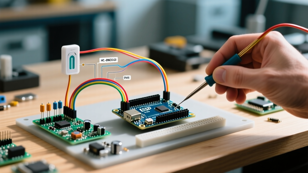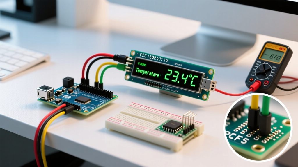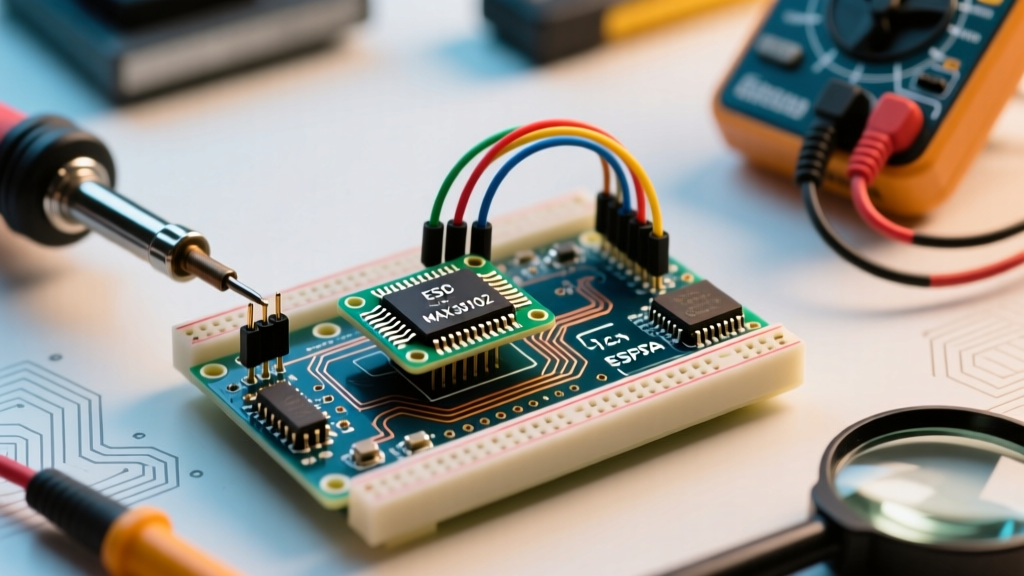

Why Your Pulse Rate Sensor Arduino Setup is Failing
Building a biometric monitor is a rite of passage for embedded engineers, but integrating a pulse rate sensor Arduino setup often ends in frustration. You wire up the sensor, upload the example code, and are immediately greeted by a serial monitor full of zeros, flatlines, or wildly fluctuating BPM values. While the analog KY-039 photoplethysmogram (PPG) modules are largely considered obsolete in 2026 due to extreme ambient light sensitivity, the digital MAX30102 and MAX30105 ICs remain the gold standard for DIY heart rate and SpO2 monitoring.
However, these high-sensitivity optical sensors are notoriously unforgiving of minor hardware and software misconfigurations. This guide bypasses generic advice and dives deep into the specific electrical, optical, and code-level failure modes of the MAX30102/MAX30105 ecosystem.
Diagnostic Matrix: Quick Symptom Matching
Before ripping apart your breadboard, match your serial monitor output to this diagnostic table to isolate the root cause.
| Symptom | Probable Root Cause | Targeted Fix |
|---|---|---|
| 'Sensor not found' or Part ID 0x00 | I2C address conflict, missing pull-ups, or counterfeit IC. | Verify 4.7kΩ pull-ups to 3.3V; check for fake chips. |
| Flatline (constant raw IR/Red values) | LED amplitude too low, or finger not covering both LED and photodetector. | Increase ledAmplitude; adjust finger placement on sensor pad. |
| Wildly erratic BPM (e.g., 40 to 180) | Saturation, ambient light leakage, or motion artifacts. | Lower ADC range; shield sensor; implement moving average filter. |
Arduino freezes during setup() | I2C bus lockup due to 5V logic on a 3.3V sensor. | Use a logic level shifter or wire SDA/SCL to 3.3V pull-ups. |
Deep Dive 1: The I2C Bus and Logic Level Trap
The most common reason a pulse rate sensor Arduino project fails on the first boot is an I2C voltage mismatch. The MAX30102 is strictly a 1.8V to 3.3V device. According to the Analog Devices MAX30102 datasheet, the absolute maximum rating for the SDA and SCL pins is 3.6V.
If you are using a 5V Arduino Uno or Mega, the microcontroller's internal I2C pull-up resistors will pull the SDA and SCL lines up to 5V. This will either silently corrupt the I2C packets, cause the Arduino's Wire library to hang indefinitely, or permanently fry the sensor's internal logic gates.
The Hardware Fix
- For 5V Arduinos: You must use a bidirectional logic level shifter (like the BSS138-based modules) between the Arduino and the sensor. Alternatively, disable the Arduino's internal pull-ups in software and use external 4.7kΩ resistors pulling SDA and SCL to the Arduino's 3.3V pin.
- For 3.3V Arduinos (ESP32, Arduino Nano 33 IoT): Ensure your breakout board actually has pull-up resistors. Many ultra-cheap clone boards omit the 4.7kΩ surface-mount resistors to save fractions of a cent. If the
Wire.endTransmission()function returns a timeout error, solder 4.7kΩ resistors between the SDA/SCL lines and the 3.3V VCC line.
Pro Tip: Always initialize the I2C bus at Fast Mode before calling the sensor's setup function. Add
Wire.setClock(400000);right afterWire.begin();. The Arduino Wire library documentation defaults to 100kHz, which can cause buffer overflows when streaming high-sample-rate PPG data.
Deep Dive 2: Optical Noise and LED Amplitude Tuning
If your I2C bus is stable but your BPM readings look like random noise, you are likely dealing with optical saturation or insufficient signal penetration. The MAX30102 uses reflective photoplethysmography. It fires an IR LED (880nm) and a Red LED (660nm) into the tissue and measures the light that bounces back to the photodetector.
Code-Level Amplitude Adjustments
When using the industry-standard SparkFun MAX3010x Sensor Library, the default LED pulse amplitude is often set to 0x1F (which translates to roughly 6.4mA). This is far too weak for most adult fingers, especially those with darker skin tones or thicker tissue.
Increase the
pulseAmplitudeRed and pulseAmplitudeIR parameters in your setup code. Start at 0x50 (approx. 16mA). If the raw values in the serial monitor are maxing out at 262,144 (the 18-bit ADC ceiling), you are saturating the photodetector. Drop the value down by increments of 0x10 until the raw AC signal shows a clear, rhythmic sine wave without clipping at the top.
Physical Placement and Pressure
A frequent physical error is pressing the finger too hard against the sensor glass. The MAX30102 requires capillary blood flow to detect the pulsatile (AC) component of the PPG signal. Pressing down firmly causes blanching—you physically squeeze the blood out of the capillary bed, resulting in a flatline DC signal. Rest your finger lightly on the sensor, ensuring the fleshy pad covers both the LED and detector windows completely to block ambient room light.
Deep Dive 3: The 2026 Counterfeit IC Epidemic
If your serial monitor outputs MAX30105 was not found. Please check wiring. but you have triple-checked your I2C connections, you likely have a counterfeit chip. The market is currently saturated with fake MAX30102 and MAX30105 modules priced around $1.50 to $2.50.
These clones often use salvaged or rejected dies that fail the Part ID verification. During the begin() function, the library reads Register 0xFF (Part ID). A genuine MAX30102 will return 0x15. Counterfeits frequently return 0x00, 0xFF, or random garbage values because the internal ROM is unprogrammed or damaged.
How to Bypass or Verify
- Read the Registers Directly: Write a custom I2C scanner script to dump the contents of registers
0xFE(Revision ID) and0xFF(Part ID). If both read0x00, the chip is dead or fake. - Comment out the Check: In some rare cases, clone chips function perfectly but have the wrong Part ID hardcoded. You can temporarily comment out the
if (partID != 0x15)check inside the library'sMAX30105.cppfile to force initialization, though optical performance is usually severely degraded. - Buy Genuine: Source your breakouts from authorized distributors (Mouser, Digi-Key, or direct from SparkFun/Adafruit). Expect to pay between $14.00 and $22.00 for a board with a verified, genuine Maxim/Analog Devices IC.
Deep Dive 4: Power Supply Decoupling and Brownouts
Optical sensors are power-hungry during the microsecond LED pulses. The IR LED can draw up to 50mA in short bursts. If you are powering the sensor directly from the Arduino Nano's onboard 3.3V LDO (which is often rated for only 50mA to 150mA total), the sudden current spikes will cause localized voltage brownouts. This resets the sensor's internal state machine mid-read, leading to corrupted FIFO buffer data.
The Capacitor Fix
To stabilize the power delivery, you must add local decoupling capacitors directly at the sensor breakout's VCC and GND pins. Solder a 100nF (0.1µF) ceramic capacitor in parallel with a 10µF tantalum or low-ESR electrolytic capacitor across the 3.3V and GND rails on the sensor board. This provides the instantaneous current required for the LED flashes without dragging down the Arduino's logic voltage.
Summary Checklist for Clean BPM Data
- Verify I2C logic levels (3.3V max on SDA/SCL).
- Confirm 4.7kΩ pull-up resistors are present on the I2C bus.
- Tune LED amplitude (
0x50baseline) to avoid ADC saturation. - Ensure light finger pressure to maintain capillary blood flow.
- Add 100nF and 10µF decoupling capacitors to the VCC rail.
By systematically addressing the electrical, optical, and power delivery constraints of the MAX30102, you can transform a noisy, unreliable pulse rate sensor Arduino project into a clinical-grade biometric monitor.