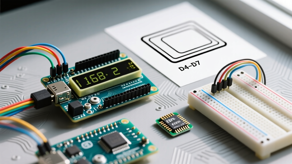

The Core Architecture: HD44780 and the I2C Expander
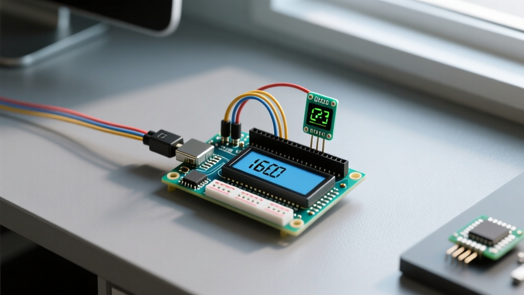
The ubiquitous 16x2 character LCD remains a staple in DIY electronics and industrial prototyping, primarily driven by the Hitachi HD44780 controller or its modern silicon clones like the SPLC780D and KS0066U. While the Arduino LiquidCrystal Reference documentation covers basic parallel wiring, modern makers in 2026 overwhelmingly prefer I2C backpacks to conserve microcontroller I/O pins. Understanding the underlying driver architecture is critical before writing a single line of code, as hardware variations directly dictate library selection and failure modes.
Natively, the HD44780 requires an 8-bit or 4-bit parallel data bus, alongside three control lines (Register Select, Read/Write, and Enable). This consumes up to 11 GPIO pins on an Arduino Uno. To solve this, manufacturers solder an I/O expander chip—almost exclusively the NXP PCF8574 or the Texas Instruments equivalent—onto the back of the LCD. This shifts the communication to the I2C bus, requiring only two pins (SDA and SCL) on the microcontroller. However, this abstraction layer introduces complex driver mapping challenges that generic tutorials frequently overlook.
Interface Comparison: Pinout, Cost, and Overhead
Choosing between direct parallel wiring and an I2C backpack involves trade-offs between refresh speed, pin economy, and software complexity. Below is a technical breakdown of the standard configurations available to Arduino developers today.
| Interface Mode | MCU Pins Required | Avg. Module Cost (2026) | Recommended Library | Bus Overhead |
|---|---|---|---|---|
| Parallel 4-bit | 6 (RS, EN, D4-D7) | $2.50 - $3.50 | LiquidCrystal | Low (Direct GPIO) |
| Parallel 8-bit | 10 (RS, RW, EN, D0-D7) | $2.50 - $3.50 | LiquidCrystal | Lowest (Direct GPIO) |
| I2C (PCF8574) | 2 (SDA, SCL) | $4.00 - $6.00 | hd44780 | High (I2C Protocol) |
| I2C (MCP23008) | 2 (SDA, SCL) | $7.00 - $9.00 | Adafruit_MCP23008 | High (I2C Protocol) |
While the I2C interface introduces protocol overhead (start/stop conditions, ACK/NACK bits, and addressing), the human eye cannot perceive the latency difference when updating a 32-character display. The primary advantage of I2C is architectural cleanliness, freeing up digital pins for rotary encoders, limit switches, or additional sensors.
The Library War: Moving Beyond Legacy Code
The most common point of failure when integrating an Arduino and LCD 16x2 module is not hardware; it is software. Specifically, it is the reliance on outdated, hardcoded I2C libraries.
Why LiquidCrystal_I2C is Failing Makers
For years, the LiquidCrystal_I2C library (often associated with Frank de Brabander or various GitHub forks) was the default recommendation. This library requires you to manually define the I2C address and the exact pin mapping between the PCF8574 expander outputs (P0-P7) and the HD44780 inputs (RS, RW, EN, D4-D7, Backlight).
The Clone Problem: Because there is no standardized schematic for cheap I2C backpacks manufactured overseas, the internal wiring varies wildly. One manufacturer might route P0 to the Register Select (RS) pin, while another routes P0 to the Backlight control. If you use a hardcoded library and guess the pin mapping incorrectly, the LCD will either display solid black blocks, remain entirely blank, or exhibit scrambled text.
The Gold Standard: hd44780 by Bill Perry
To eliminate the guesswork, the open-source community has universally adopted the hd44780 Library Repository maintained by Bill Perry. Unlike legacy libraries, the hd44780_I2Cexp class includes an auto-diagnostic engine. Upon initialization, it scans the I2C bus for the backpack, identifies the specific PCF8574 variant, and mathematically deduces the pin mapping by toggling outputs and reading the HD44780 busy flag. It then caches this mapping in the microcontroller's EEPROM for instant subsequent boot-ups.
Step-by-Step Driver Implementation (I2C)
To implement the modern standard for Arduino and LCD 16x2 integration, install the hd44780 library via the Arduino IDE Library Manager. Do not install the legacy LiquidCrystal_I2C alongside it, as header file collisions will cause compilation errors.
#include <Wire.h>
#include <hd44780.h>
#include <hd44780ioClass/hd44780_I2Cexp.h>

// Instantiate the auto-detecting I2C expander object
hd44780_I2Cexp lcd;

void setup() {
  // Initialize LCD with 16 columns and 2 rows
  // The library auto-detects the I2C address and pin mapping
  lcd.begin(16, 2);

  // Optional: Turn on the backlight
  lcd.backlight();

  lcd.setCursor(0, 0);
  lcd.print("ElectricalFlux");
  lcd.setCursor(0, 1);
  lcd.print("Driver Guide");
}

void loop() {
  // Static display for demonstration
}
Advanced Troubleshooting & Hardware Edge Cases
Even with the correct library, hardware quirks specific to the HD44780 and PCF8574 chips can stall your project. Here are the advanced failure modes that separate novices from experts.
1. The I2C Address Trap: PCF8574 vs. PCF8574A
Many makers blindly assume their I2C backpack address is 0x27. However, manufacturers use two different chips that look identical to the naked eye. According to the NXP PCF8574/74A Datasheet, the standard PCF8574 has base address 0x20 (yielding 0x27 when all address pins are pulled high). The PCF8574A variant has a base address of 0x38 (yielding 0x3F when pulled high). If your I2C scanner returns 0x3F, you have the 'A' variant. The hd44780 library handles this automatically, but if you are writing bare-metal I2C commands, this distinction is critical.
2. Contrast Voltage (V0) and the Missing Trimpot
The HD44780 requires a specific voltage delta between VDD (5V) and V0 (Pin 3) to bias the liquid crystals. The optimal voltage for V0 is typically around 0.4V to 0.6V. Most I2C backpacks include a blue 10kΩ trimpot (usually a 3006P multi-turn potentiometer) to create this voltage divider. If you are using a raw parallel LCD without a trimpot, you must supply a negative voltage to V0 (around -1V to -2V) if running on 3.3V logic, or use a precise PWM-filtered DAC output. A floating V0 pin will result in a completely blank screen, regardless of correct code.
3. Backlight Jumper and Current Sinking Limits
Most I2C backpacks feature a 2-pin jumper labeled "LED" or "Backlight". This jumper controls whether the backlight is permanently on or controlled via software. However, understanding the current path is vital. The PCF8574 is an open-drain, current-sinking device. It can safely sink up to 25mA per I/O pin. The backpack uses an onboard NPN transistor (often an MMBT3904) to switch the backlight array, which can draw 80mA to 120mA. If you remove the jumper and attempt to drive the backlight directly from a PCF8574 pin without utilizing the transistor circuit, you will exceed the chip's absolute maximum ratings and permanently destroy the I/O expander.
4. I2C Bus Capacitance and Pull-Up Resistors
The I2C specification limits total bus capacitance to 400pF. A standard 16x2 LCD backpack adds roughly 15pF to 20pF of capacitance. If you are daisy-chaining multiple displays, sensors, and long ribbon cables, the signal edges will degrade, leading to corrupted characters on the LCD. For bus lengths exceeding 30cm, drop the standard 4.7kΩ pull-up resistors to 2.2kΩ to sharpen the rise times, or insert a P82B96 I2C bus buffer IC to isolate the display's capacitance from the main microcontroller bus.
Summary: Best Practices for 2026
- Always use I2C: Unless you are operating in a high-EMI environment where I2C is unreliable, the 2-pin I2C backpack is superior for prototyping and final PCB integration.
- Ditch Legacy Libraries: Uninstall
LiquidCrystal_I2Cand standardLiquidCrystalif you are using a backpack. Rely exclusively on thehd44780library for auto-detection and EEPROM caching. - Verify Hardware: Inspect your backpack for the contrast trimpot and ensure the backlight jumper is utilizing the onboard transistor switching circuit.
- Manage Pull-Ups: Ensure your Arduino's internal pull-ups are disabled in software when using external 4.7kΩ or 2.2kΩ physical pull-up resistors on the SDA/SCL lines to prevent bus contention.
By mastering the intersection of hardware schematics and modern driver libraries, the Arduino and LCD 16x2 combination transforms from a frustrating source of blank screens into a highly reliable, low-overhead telemetry display for your embedded systems.