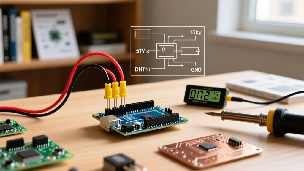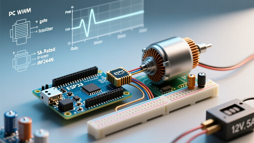

When integrating an arduino with pwm for real-world inductive loads like DC motors, solenoids, or high-power LED arrays, the standard analogWrite() function often falls short. Hobbyist tutorials rarely address the acoustic noise, electromagnetic interference (EMI), and destructive voltage spikes that occur when switching high-current loads at default microcontroller frequencies. This guide details the engineering required to build a robust, 5A DC motor speed controller, shifting from theoretical breadboard concepts to a deployable 20kHz ultrasonic PWM circuit.
The Hidden Pitfalls of Default analogWrite()
By default, most PWM pins on an ATmega328P-based board operate at approximately 490Hz. While sufficient for dimming a standard 5mm LED, applying a 490Hz square wave to a DC motor's inductive windings causes severe magnetostriction. The motor's internal laminations physically vibrate at the switching frequency, resulting in an audible, high-pitched whine. Furthermore, 490Hz switching generates significant EMI, which can corrupt nearby I2C sensor buses or analog ADC readings.
Engineering Rule of Thumb: For audio-sensitive or EMI-critical environments, motor drive PWM frequencies must be pushed above 18kHz (ultrasonic) to eliminate acoustic noise and minimize inductive ripple current.
Bill of Materials (BOM): 5A Ultrasonic PWM Driver
As of 2026, logic-level MOSFETs remain the most cost-effective method for switching moderate DC loads without the overhead of dedicated H-bridge ICs. Below is the verified BOM for a unidirectional speed controller.
| Component | Specification / Part Number | Est. Cost (2026) |
|---|---|---|
| Microcontroller | Arduino Nano Every (ATmega4809) | $11.50 |
| Switching Element | IRLZ44N N-Channel Logic-Level MOSFET | $1.20 |
| Flyback Diode | 1N5819 Schottky Rectifier (1A, 40V) | $0.15 |
| Gate Resistor | 100Ω Carbon Film (1/4W) | $0.02 |
| Pull-Down Resistor | 10kΩ Carbon Film (1/4W) | $0.02 |
| Total BOM Cost | Excluding motor and power supply | ~$12.89 |
The Logic-Level MOSFET Selection Trap
A pervasive mistake in maker communities is pairing an Arduino with the ubiquitous IRF520 MOSFET module. The IRF520 is a standard-level MOSFET requiring 10V at the gate to fully enhance and achieve its rated $R_{DS(on)}$. When driven by an Arduino's 5V logic pin, the IRF520 operates in its linear (ohmic) region, acting as a variable resistor rather than a closed switch. At 5A, an IRF520 driven at 5V will dissipate over 3W of heat, requiring massive active cooling and severely reducing efficiency.
Conversely, the IRLZ44N (note the 'L' for Logic-level) is specifically engineered to fully enhance at $V_{GS} = 4V$ to $5V$. This ensures the $R_{DS(on)}$ drops to its datasheet minimum of 22mΩ, keeping thermal losses below 1W at continuous 5A loads. Always verify the $V_{GS(th)}$ and the $R_{DS(on)}$ vs Gate Voltage graph in the component datasheet before purchasing.
Circuit Architecture & Protection Mechanics
Interfacing an arduino with pwm outputs directly to a MOSFET gate seems trivial, but omitting passive protection components is the primary cause of field failures in DIY automation.
The Gate Resistor and Pull-Down Imperative
A MOSFET gate behaves like a small capacitor (the IRLZ44N has an input capacitance of roughly 3300pF). When the Arduino pin goes HIGH, it attempts to charge this capacitor instantly. This inrush current can exceed the ATmega4809's absolute maximum pin rating of 20mA, degrading the silicon over time. Placing a 100Ω resistor in series with the gate limits the charging current to a safe ~50mA peak while still allowing switching times in the nanosecond range.
Additionally, during the Arduino's boot sequence, GPIO pins float in a high-impedance state. Without a 10kΩ pull-down resistor tying the gate to ground, stray EMI can partially turn on the MOSFET, causing the motor to stutter or the MOSFET to overheat in its linear region before your code even begins executing.
Managing Inductive Kickback
When the MOSFET switches OFF, the motor's collapsing magnetic field generates a massive reverse voltage spike (inductive kickback). Without a path for this energy, it will avalanche through the MOSFET, destroying it instantly. A 1N5819 Schottky diode placed in reverse-bias across the motor terminals provides a low-resistance recirculation path for this flyback current. We specify a Schottky diode over a standard 1N4007 because its near-zero reverse recovery time prevents high-frequency ringing during the PWM OFF cycle. For deeper insights into inductive load switching, refer to the SparkFun Pulse Width Modulation Tutorial.
Shifting Frequencies: Escaping the 490Hz Whine
To achieve silent operation, we must reconfigure the microcontroller's hardware timers. On the Arduino Nano Every (and standard Uno/Nano), Pins 9 and 10 are tied to Timer1. By manipulating the Timer/Counter Control Registers (TCCR), we can increase the base frequency to roughly 31.25kHz, well beyond human hearing.
// Pin 9 PWM setup for 31.25kHz (Ultrasonic)
void setup() {
  pinMode(9, OUTPUT);

  // Clear Timer1 control registers
  TCCR1A = 0;
  TCCR1B = 0;

  // Set Fast PWM mode, non-inverting on OC1A (Pin 9)
  TCCR1A |= (1 << COM1A1) | (1 << WGM11);

  // Set prescaler to 1 (no prescaling) and enable Fast PWM 10-bit
  // 16MHz / (1 * 510) = ~31.37kHz
  TCCR1B |= (1 << WGM12) | (1 << CS10);
}

void loop() {
  // Ramp motor speed up and down
  for (int duty = 0; duty <= 255; duty += 5) {
    analogWrite(9, duty);
    delay(50);
  }
  for (int duty = 255; duty >= 0; duty -= 5) {
    analogWrite(9, duty);
    delay(50);
  }
}
Note: Changing Timer1 will break the default timing for the Servo library and delay() functions if they rely on the same timer architecture. Always consult the Arduino analogWrite() Reference to verify pin-to-timer mappings before altering registers.
Real-World Thermal Management & Edge Cases
Calculating steady-state heat dissipation is straightforward, but real-world edge cases dictate your thermal design. The IRLZ44N boasts an $R_{DS(on)}$ of 22mΩ when driven with 5V at the gate.
- Steady-State (5A Continuous): Power dissipation $P = I^2 \times R = 25 \times 0.022 = 0.55W$. The TO-220 package can dissipate this passively in open air without a heatsink.
- Stall Current Edge Case (15A Peak): If the motor mechanically jams, current spikes to the stall rating. $P = 225 \times 0.022 = 4.95W$. Without a heatsink, the silicon junction temperature will exceed the 175°C thermal shutdown limit in under 10 seconds, potentially causing catastrophic thermal runaway.
To mitigate this in industrial or unattended agricultural deployments, integrate an ACS712 Hall-effect current sensor in series with the motor. Program the Arduino to monitor the ADC voltage; if the current exceeds 8A for more than 200 milliseconds, immediately set the PWM duty cycle to 0 and trigger a fault flag.
Frequently Asked Questions
Can I use an H-Bridge IC like the L298N instead of a discrete MOSFET?
While the L298N provides bidirectional control, it utilizes outdated bipolar junction transistor (BJT) technology. The L298N suffers from a combined voltage drop of roughly 2V to 3V across its internal Darlington pairs. At 5A, this equates to 10W–15W of wasted heat, necessitating large heatsinks. For unidirectional control, a discrete logic-level MOSFET is vastly superior in efficiency, cost, and thermal management.
Why is my motor twitching when the Arduino powers on?
This occurs because the GPIO pins are in a high-impedance (floating) state during the bootloader sequence. Ambient electromagnetic noise induces a voltage on the floating gate pin, partially turning on the MOSFET. The 10kΩ pull-down resistor detailed in the BOM explicitly prevents this by holding the gate at 0V until the pinMode() function executes.
Summary of Deployment Best Practices
Transitioning an arduino with pwm from a breadboard prototype to a permanent installation requires respecting the physics of inductive loads. By utilizing logic-level MOSFETs, enforcing strict gate and flyback protection, and manipulating hardware timers to achieve ultrasonic switching frequencies, you eliminate acoustic noise and protect your microcontroller from fatal voltage transients.