
Understanding Acceleration Sensors in Microcontroller Projects
When building motion-aware electronics, an acceleration sensor is the foundational component for measuring proper acceleration—the physical force experienced by an object relative to freefall. Unlike GPS modules that track coordinate velocity, accelerometers measure G-force, making them indispensable for tilt sensing, vibration monitoring, and inertial navigation. For beginners tackling an acceleration sensor Arduino project, the market offers dozens of microelectromechanical systems (MEMS) chips. However, navigating logic levels, I2C addresses, and raw data parsing can quickly overwhelm newcomers.
This tutorial provides a deep-dive, step-by-step guide to interfacing the most ubiquitous 6-axis IMU (Inertial Measurement Unit) with an Arduino: the TDK InvenSense MPU-6050. We will cover hardware selection, voltage-safe wiring, and firmware configuration to extract reliable, calibrated G-force data.
Choosing the Right Breakout Board for Your Build
Before soldering headers, it is critical to select a sensor that matches your project's power and precision constraints. While the MPU-6050 is the default choice for most hobbyist drones and balancing robots, other ICs excel in low-power wearables. Below is a 2026 market comparison of the three most common MEMS accelerometers available on breakout boards.
| Sensor IC | Manufacturer | Axes & Features | Typical Price (2026) | I2C Address | Best Use Case |
|---|---|---|---|---|---|
| MPU-6050 | TDK InvenSense | 6-Axis (Accel + Gyro), DMP | $2.50 - $4.50 | 0x68 / 0x69 | Robotics, drones, motion tracking |
| ADXL345 | Analog Devices | 3-Axis, Tap/Freefall Detect | $4.50 - $7.00 | 0x53 / 0x1D | Low-power wearables, step counting |
| LIS3DH | STMicroelectronics | 3-Axis, Ultra-low power | $3.00 - $5.50 | 0x18 / 0x19 | Battery IoT logging, shock detection |
Note: According to the official TDK InvenSense MPU-6050 documentation, the chip includes an embedded Digital Motion Processor (DMP) capable of hardware-accelerated sensor fusion, offloading complex quaternion math from your Arduino's CPU.
Step-by-Step Hardware Wiring
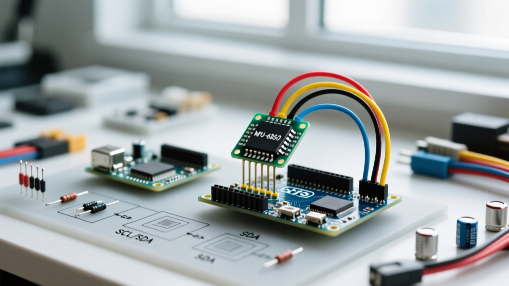
The most common point of failure in beginner I2C projects is a logic-level mismatch. The bare MPU-6050 silicon operates strictly at 3.3V. However, most inexpensive breakout boards (like those from generic marketplaces) include an onboard AMS1117-3.3 LDO voltage regulator and 4.7kΩ pull-up resistors tied to the VCC pin.
Pinout and I2C Bus Considerations
If your breakout board features an LDO and logic-level shifting MOSFETs, you can safely connect it to a 5V Arduino Uno. If you are using a bare-bones breakout without voltage regulation, you must use a 3.3V microcontroller (like the Arduino Nano 33 IoT or a 3.3V Pro Mini) to avoid permanently damaging the sensor's silicon.
- VCC: Connect to 5V (if breakout has LDO) or 3.3V (bare module).
- GND: Connect to Arduino GND. Ensure a common ground to prevent I2C bus lockups.
- SCL: Connect to Arduino A5 (hardware I2C clock on ATmega328P).
- SDA: Connect to Arduino A4 (hardware I2C data on ATmega328P).
- XDA / XCL: Leave unconnected (used for auxiliary I2C master modes).
- AD0: Leave unconnected to ground (sets I2C address to 0x68). Tie to VCC to change address to 0x69.
- INT: Connect to a digital interrupt pin (e.g., D2) if you plan to use hardware interrupts for data-ready signals.
Pro-Tip on I2C Capacitance: The Arduino Wire Library adheres to the standard I2C specification, which limits total bus capacitance to 400pF. If you are daisy-chaining multiple sensors or using long jumper wires (over 12 inches), signal degradation will occur. Keep I2C traces short and use active pull-ups if bus capacitance exceeds limits.
Writing the Arduino Firmware
While you can manually write to the MPU-6050's registers using raw Wire.h commands, utilizing a unified sensor library drastically reduces development time and handles the complex two's complement bitwise math required to parse raw 16-bit register data into usable G-force floats.
Library Setup and Initialization
Open the Arduino IDE Library Manager and install the Adafruit MPU6050 and Adafruit Unified Sensor libraries. As detailed in Adafruit's comprehensive MPU-6050 guide, the Unified Sensor framework standardizes data output across different hardware, making it easy to swap an MPU-6050 for an ADXL345 later without rewriting your core logic.
#include <Adafruit_MPU6050.h>
#include <Adafruit_Sensor.h>
#include <Wire.h>

Adafruit_MPU6050 mpu;

void setup() {
  Serial.begin(115200);
  while (!Serial) delay(10);

  // Initialize I2C and check for sensor presence
  if (!mpu.begin(0x68)) {
    Serial.println('Failed to find MPU6050 chip');
    while (1) { delay(10); }
  }
  Serial.println('MPU6050 Found!');

  // Configure Accelerometer Range and Filter
  mpu.setAccelerometerRange(MPU6050_RANGE_8_G);
  mpu.setGyroRange(MPU6050_RANGE_500_DEG);
  mpu.setFilterBandwidth(MPU6050_BAND_21_HZ);

  delay(100);
}
Reading and Parsing the G-Force Data
Instead of reading raw hex values from the I2C FIFO buffer, the library populates a sensors_event_t struct. This struct automatically applies the sensitivity scale factor (e.g., 4096 LSB/g for the ±8G range) to output standard SI units (m/s²).
void loop() {
  sensors_event_t a, g, temp;
  mpu.getEvent(&a, &g, &temp);

  // Output Acceleration in m/s^2
  Serial.print('Accel X:'); Serial.print(a.acceleration.x);
  Serial.print(', Y:'); Serial.print(a.acceleration.y);
  Serial.print(', Z:'); Serial.print(a.acceleration.z);
  Serial.println(' m/s^2');

  // To convert to G-force, divide by 9.80665
  float z_g = a.acceleration.z / 9.80665;
  Serial.print('Z-Axis G-Force: '); Serial.println(z_g);

  delay(100); // 10Hz polling rate
}
Real-World Calibration and Edge Cases
Getting data to print to the serial monitor is only the first step. Real-world deployment introduces environmental noise and hardware quirks that beginners must account for.
Temperature Drift and Zero-G Offset
MEMS accelerometers are inherently susceptible to temperature drift. The MPU-6050 features an onboard temperature sensor, but its primary purpose is for the DMP to compensate the gyroscope, not the accelerometer. If your project requires high-precision static tilt measurement (e.g., a digital inclinometer), you must perform a 6-point calibration on a machined, perfectly level surface to calculate the zero-G offset and scale factor errors for each axis.
Filtering High-Frequency Motor Noise
If your acceleration sensor is mounted on a chassis with DC motors or servos, the mechanical vibrations will saturate the sensor's ADC, resulting in clipped, noisy data. Notice the line mpu.setFilterBandwidth(MPU6050_BAND_21_HZ); in the setup code above. This engages the internal digital low-pass filter (DLPF). By setting the bandwidth to 21Hz, you effectively reject the high-frequency acoustic noise generated by typical hobby motors (which often vibrate between 100Hz and 300Hz), leaving only the macro-movements of the vehicle.
Frequently Asked Questions
Why does my Arduino I2C bus hang or freeze?
I2C lockups usually occur due to missing pull-up resistors, a voltage mismatch where the 3.3V sensor cannot pull the 5V Arduino line high enough to register a logic '1', or a loose GND connection. Always verify your breakout board's pull-up configuration and ensure SDA/SCL are not accidentally swapped.
Can I use multiple MPU-6050 sensors on the same Arduino?
Yes, but only two. The MPU-6050 only has one address pin (AD0), allowing you to toggle between I2C addresses 0x68 and 0x69. If you need to daisy-chain four or more sensors, you must use an I2C multiplexer like the TCA9548A, which routes the I2C bus to separate isolated channels.
What is the difference between the MPU-6050 and the newer MPU-9250?
The MPU-9250 is a 9-axis IMU that adds an AK8963 magnetometer (compass) to the 6-axis accel/gyro package. However, the MPU-9250 is largely obsolete for new designs in 2026, having been replaced by the ICM-20948. For pure acceleration and tilt sensing, the cheaper MPU-6050 remains the most cost-effective and well-documented choice for Arduino beginners.