
The HD44780 Controller: Why the 1602A Persists in 2026
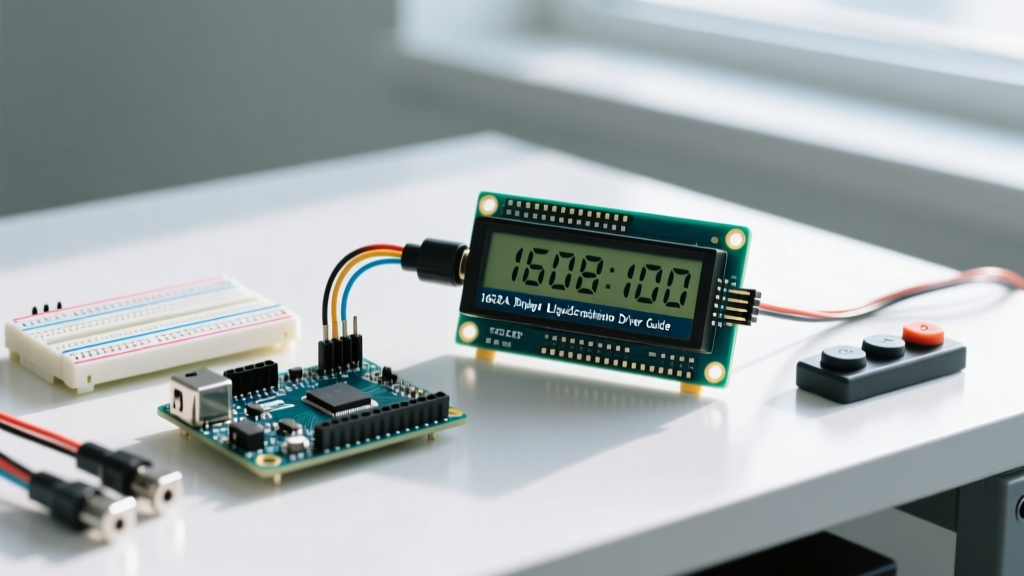
Despite the rapid proliferation of high-resolution OLEDs and IPS TFT screens, the 1602A LCD display remains a cornerstone of microcontroller projects. Driven by the ubiquitous Hitachi HD44780 controller (or modern clones like the SPLC780D), the 1602A offers unmatched readability in direct sunlight, extreme temperature tolerance, and a barebones module cost that hovers between $2.00 and $4.00 in 2026. For industrial HMIs, retro-computing interfaces, and low-power diagnostic tools, mastering the 1602A LCD display Arduino integration is a mandatory skill for embedded engineers.
This comprehensive driver and library guide moves beyond basic blink-and-print tutorials. We will dissect the hardware architecture, compare parallel versus I2C backpack topologies, and detail the modern software ecosystem that makes driving these displays effortless on both 5V AVR and 3.3V ARM/ESP architectures.
Hardware Architecture: Parallel vs. I2C Backpack
The raw 1602A module exposes a 16-pin header. Driving this natively requires a 4-bit parallel bus, consuming 6 GPIO pins on your microcontroller. To mitigate this pin-tax, the market standardized on the PCF8574 I/O expander backpack, reducing the interface to a 4-pin I2C bus. Below is a technical comparison of both paradigms.
| Feature | 4-Bit Parallel (Native) | I2C Backpack (PCF8574) |
|---|---|---|
| GPIO Consumption | 6 Pins (RS, EN, D4-D7) | 2 Pins (SDA, SCL) |
| Bus Speed | ~1-2 MHz (Direct GPIO) | 100 kHz / 400 kHz (I2C Limit) |
| Library Overhead | Low (Direct port manipulation) | Medium (I2C protocol framing) |
| Wiring Complexity | High (Prone to loose Dupont wires) | Low (Standardized 4-pin JST) |
| Cost (2026 Avg) | $2.50 (Display only) | $3.80 (Display + Backpack) |
The I2C Address Trap: PCF8574T vs. PCF8574AT
One of the most common failure points for beginners is the I2C address mismatch. According to the Texas Instruments PCF8574 Datasheet, the standard PCF8574T chip (commonly found on blue/green backpacks) defaults to the I2C address 0x27. However, the PCF8574AT variant defaults to 0x3F. If your display fails to initialize, scanning the I2C bus using the standard Arduino Wire scanner sketch is mandatory before assuming a hardware defect.
The Driver Ecosystem: Choosing the Right Library
Historically, developers relied on the built-in Arduino LiquidCrystal Reference library for parallel wiring, and the fragmented LiquidCrystal_I2C forks for backpacks. In 2026, this fragmented approach is obsolete.
Expert Recommendation: Deprecate
LiquidCrystal_I2Cin your workflow. The undisputed gold standard for HD44780 displays is the hd44780 Library by Bill Perry. It features automatic I2C address detection, automatic pin-mapping for non-standard backpacks, and built-in diagnostics.
Installing and Configuring the hd44780 Library
The hd44780 library utilizes an object-oriented architecture. For I2C backpacks, you must include the specific hd44780_I2Cexp class. This class automatically probes the I2C bus, identifies the PCF8574 expander, and maps the GPIO pins to the LCD's RS, RW, EN, and D4-D7 lines, completely eliminating the manual pin-mapping headaches that plagued older libraries.
#include <Wire.h>
#include <hd44780.h>
#include <hd44780ioClass/hd44780_I2Cexp.h>

hd44780_I2Cexp lcd; // Auto-detects address and pin mapping

void setup() {
  lcd.begin(16, 2); // Initialize 16x2 display
  lcd.backlight();
  lcd.print("ElectricalFlux");
}
Critical Wiring Considerations & Edge Cases
Software can only compensate for so much. The physical layer of the 1602A LCD display Arduino integration requires strict adherence to electrical tolerances.
1. The Contrast Pin (V0 / Pin 3) Voltage Divider
Pin 3 (V0) controls the liquid crystal bias voltage. Many tutorials suggest a 10k potentiometer. However, modern high-efficiency 1602A panels require a V0 voltage between 0.4V and 0.8V relative to VSS (Ground). If you connect a 10k pot across 5V and GND, the usable contrast range is limited to the bottom 5% of the dial, making tuning hyper-sensitive. Actionable Fix: Use a 1kΩ fixed resistor tied directly from V0 to GND, or drive V0 with a 5V PWM pin filtered by a 10µF capacitor for software-controlled contrast.
2. I2C Pull-Up Resistors
The PCF8574 backpack utilizes open-drain outputs for the I2C bus. While some microcontrollers (like the ESP32) enable internal weak pull-ups, they are often insufficient (typically 40kΩ) for long wire runs. If your I2C bus hangs or drops packets, solder 4.7kΩ pull-up resistors between SDA/VCC and SCL/VCC directly on the backpack header.
3. 3.3V Logic Level Shifting (ESP32 / RP2040)
The 1602A requires a 5V power supply and expects 5V logic levels on the SDA/SCL lines. Connecting a 3.3V MCU directly to a 5V I2C backpack can result in unrecognized logic HIGHs or, worse, back-feeding voltage into the MCU's GPIO pins. For robust 3.3V integration, use a bi-directional logic level converter (like the BSS138 MOSFET circuit) or power the LCD via a dedicated 5V rail while shifting the I2C lines.
Advanced Feature: Custom CGRAM Characters
The HD44780 controller features 64 bytes of Character Generator RAM (CGRAM), allowing you to define up to eight custom 5x8 pixel characters. This is essential for rendering custom battery icons, signal strength bars, or proprietary brand logos.
Below is the byte-map structure for creating a custom 'Wi-Fi' signal icon:
byte wifiIcon[8] = {
  0b00000,
  0b01110,
  0b10001,
  0b01110,
  0b00100,
  0b00100,
  0b00000,
  0b00000
};

void setup() {
  lcd.begin(16, 2);
  lcd.createChar(0, wifiIcon); // Store in CGRAM slot 0
  lcd.setCursor(0, 0);
  lcd.write(byte(0)); // Render custom character
}
Real-World Troubleshooting Matrix
When a 1602A display fails to operate correctly, the symptoms usually point to specific hardware or software faults. Use this diagnostic matrix to isolate the issue rapidly.
| Symptom | Probable Cause | Engineering Solution |
|---|---|---|
| Top row shows solid white/black blocks | No communication; LCD is uninitialized or stuck in 8-bit mode. | Check I2C address. Power cycle the LCD to reset the HD44780 state machine. |
| Text is visible but extremely faint | V0 (Pin 3) voltage is too high (near 5V). | Ensure V0 is pulled to GND via a 1kΩ resistor or 10kΩ potentiometer. |
| Display works, but backlight is off | Missing jumper or blown backlight resistor. | Check the 'LED' jumper on the I2C backpack. Measure 5V on Pin 15 (Anode). |
| Garbage characters / shifting text | I2C bus noise or missing pull-up resistors. | Add 4.7kΩ pull-ups to SDA/SCL. Keep I2C traces under 30cm. |
MCU freezes upon lcd.print() | I2C bus lockup due to missing ACK. | Verify logic levels. Implement I2C bus watchdog timeout in software. |
Summary
Integrating a 1602A LCD display into an Arduino project in 2026 is less about battling hardware limitations and more about leveraging modern, intelligent driver libraries. By abandoning legacy parallel wiring in favor of I2C backpacks, utilizing the auto-diagnostic hd44780 library, and respecting the analog requirements of the V0 contrast pin and I2C pull-ups, you guarantee a rock-solid, industrial-grade user interface for pennies on the dollar.