
The Hardware-Software Paradigm: Why One Size Doesn't Fit All
When beginners search for arduino code for servo motor projects, they usually find a generic sweep tutorial using the TowerPro SG90. However, as you scale up to high-torque metal-gear servos or high-voltage digital models, the standard code and wiring paradigms fail—often resulting in stripped gears, microcontroller brownouts, or burned-out driver circuits. In 2026, the hobbyist and robotics market offers a vast array of actuators, and writing robust Arduino code requires understanding the specific PWM (Pulse Width Modulation) characteristics, current draw, and mechanical limits of your chosen component.
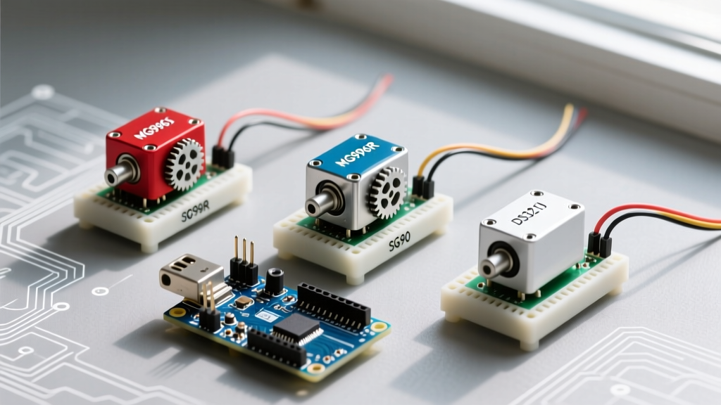
This guide compares four distinct classes of servos—the micro SG90, the heavy-duty MG996R, the high-voltage digital DS3218, and the continuous rotation FS90R. We will break down the exact Arduino code for servo motor control required for each, alongside the critical power architectures needed to keep your project alive.
Component Comparison Matrix
| Model | Type | Stall Torque (6V) | Operating Voltage | Avg. Price (2026) | Code Nuance |
|---|---|---|---|---|---|
| TowerPro SG90 | Analog Micro | 1.8 kg-cm | 4.8V - 6.0V | $2.50 | Standard 0-180° mapping |
| MG996R | Analog Metal Gear | 13.0 kg-cm | 4.8V - 6.6V | $9.50 | Requires pulse width calibration |
| Freedo DS3218 | Digital Waterproof | 25.0 kg-cm | 6.0V - 8.4V | $22.00 | Microsecond precision, HV BEC needed |
| FS90R | Continuous Rotation | N/A (Speed) | 4.8V - 6.0V | $6.00 | Write maps to speed/direction |
1. TowerPro SG90: The Baseline Standard
The SG90 is the ubiquitous blue micro-servo found in almost every starter kit. It features plastic gears and an internal potentiometer for position feedback. Because its stall current is relatively low (around 220mA), it can technically be powered directly from the Arduino's 5V pin for light loads, though this is generally discouraged for long-term reliability.
Standard Arduino Code for SG90
The standard Arduino Servo Library handles the SG90 perfectly out of the box. The write() function accepts an angle from 0 to 180, which the library translates to a PWM pulse width between 544 and 2400 microseconds.
#include <Servo.h>

Servo sg90;

void setup() {
  sg90.attach(9); // Attach signal wire to Pin 9
}

void loop() {
  sg90.write(0);   // Move to 0 degrees
  delay(1000);
  sg90.write(90);  // Move to center
  delay(1000);
  sg90.write(180); // Move to 180 degrees
  delay(1000);
}
Failure Mode: If your SG90 jitters or your Arduino resets randomly, you are experiencing a brownout. The USB port on most PCs limits current to 500mA. If the servo encounters mechanical resistance, it draws peak stall current, dropping the voltage below the ATmega328P's brownout detection threshold (typically 2.7V - 4.3V).
2. MG996R: High-Torque and Pulse Calibration
The MG996R is a staple in RC cars and robotic arms, boasting metal gears and 13 kg-cm of torque. However, its stall current can exceed 2.5 Amps under load.
CRITICAL WARNING: Never power an MG996R from the Arduino's 5V or VIN pins. Doing so will likely melt the Arduino's onboard voltage regulator or trace lines. You must use an external 5V/6V power supply rated for at least 3A, sharing a common ground with the Arduino.
Calibrating the Arduino Code for MG996R
Unlike the SG90, cheap MG996R clones often have slight potentiometer variances. Sending a hard 0 or 180 command can force the servo past its physical mechanical stops, causing a continuous, destructive humming sound that strips the internal metal gears or burns out the DC motor. To prevent this, we restrict the PWM pulse width in the attach() function.
#include <Servo.h>

Servo mg996r;

void setup() {
  // Restrict pulse width to prevent mechanical end-stop grinding
  // Min pulse: 600us, Max pulse: 2300us
  mg996r.attach(9, 600, 2300);
}

void loop() {
  mg996r.write(10);  // Safe minimum position
  delay(1500);
  mg996r.write(170); // Safe maximum position
  delay(1500);
}
According to Pololu's RC Servo Guide, standard RC pulses range from 1000µs to 2000µs, but most modern servos respond to 500µs–2500µs. Finding the exact safe minimum and maximum for your specific MG996R batch requires manual testing using a serial monitor and incremental microsecond adjustments.
3. Freedo DS3218: Digital Precision and High Voltage
The DS3218 is a 25 kg-cm digital servo designed for harsh environments (waterproof/dustproof). Digital servos use an internal microcontroller to sample the potentiometer and drive the motor at a much higher frequency than analog servos, resulting in tighter holding torque and faster response times. Crucially, the DS3218 operates at 6.0V to 8.4V (2S LiPo voltage).
High-Voltage Code and Architecture
If you plug a DS3218 into a standard 5V Arduino rail, it will operate sluggishly or not at all, potentially drawing excessive current trying to compensate. You must power it via a 7.4V LiPo battery and a high-current BEC (Battery Eliminator Circuit). Furthermore, digital servos respond better to direct microsecond commands rather than abstracted degree angles.
#include <Servo.h>

Servo ds3218;

void setup() {
  // Digital servos prefer exact microsecond targeting
  ds3218.attach(9, 500, 2500);
}

void loop() {
  // Move to specific microsecond positions for digital precision
  ds3218.writeMicroseconds(1000);
  delay(2000);
  ds3218.writeMicroseconds(1500); // Center
  delay(2000);
  ds3218.writeMicroseconds(2000);
  delay(2000);
}
Information Gain: Digital servos like the DS3218 constantly draw small pulses of current to maintain position, even when stationary. This causes a higher baseline power draw compared to analog servos. If your project runs on a limited battery budget, consider using the detach() function in your code once the servo reaches its target position, provided your mechanical load doesn't require active holding torque.
4. FS90R: The Continuous Rotation Paradigm Shift
The FS90R is physically identical to standard micro servos but lacks the internal potentiometer and mechanical hard stops. Instead of moving to a specific angle, the arduino code for servo motor control here dictates speed and direction.
Speed and Direction Mapping
In continuous rotation servos, the 90° position (or 1500µs pulse) represents a dead-band where the motor stops. Values below 90 spin the servo in one direction (with 0 being full speed reverse), and values above 90 spin it in the opposite direction (with 180 being full speed forward).
#include <Servo.h>

Servo fs90r;

void setup() {
  fs90r.attach(9);
}

void loop() {
  fs90r.write(0);   // Full speed counter-clockwise
  delay(2000);
  fs90r.write(90);  // STOP (Might require calibration to 88 or 92)
  delay(1000);
  fs90r.write(180); // Full speed clockwise
  delay(2000);
  fs90r.write(90);  // STOP
  delay(5000);
}
Edge Case Troubleshooting: Due to manufacturing tolerances, the "stop" value on an FS90R is rarely exactly 90. If your servo slowly creeps when commanded to stop, use a small flathead screwdriver to turn the calibration screw on the bottom of the unit, or adjust the code to output 89 or 91 until the motor achieves a true zero-state.
Designing a Robust Power Architecture
Writing flawless code is useless if your power delivery fails. When integrating multiple servos (e.g., a 4-DOF robotic arm using MG996Rs), follow this power topology:
- Power Source: Use a 5V 10A switching power supply (e.g., Mean Well LRS-50-5) for analog servos, or a 2S/3S LiPo with a 10A UBEC for digital/high-voltage servos.
- Common Ground: The ground (GND) of the external power supply must be connected to the GND pin of the Arduino. Without a shared reference ground, the PWM signal from the Arduino will be unreadable to the servo, resulting in erratic spinning.
- Signal Isolation: For highly sensitive projects, consider using an opto-isolator or a dedicated PCA9685 I2C PWM driver board. The PCA9685 offloads PWM generation from the Arduino's hardware timers, eliminating software-induced servo jitter caused by interrupt conflicts (e.g., when using
Servo.halongsideSoftwareSerial).
Frequently Asked Troubleshooting Questions
Why does my servo jitter when I use the Serial Monitor?
The standard Arduino Servo.h library relies on Timer1. If you are using libraries that also rely on hardware timers or frequent interrupts (like software-based serial communication or high-frequency sensor polling), the PWM signal can be disrupted. Switching to a hardware I2C driver like the PCA9685 resolves this entirely.
Can I use a 9V battery to power an MG996R?
No. Standard 9V alkaline batteries have a very high internal resistance and cannot deliver the 2.5A peak current required by an MG996R. The voltage will instantly collapse under load. Furthermore, 9V exceeds the 6.6V maximum rating of the MG996R, which will destroy the internal driver IC. Always use high-discharge LiPo batteries or high-amperage 5V/6V DC wall adapters.
How do I measure the exact pulse width of my servo?
If you are reverse-engineering a commercial servo, you can use an oscilloscope or a logic analyzer to read the PWM signal from a standard RC receiver. Alternatively, you can write a simple Arduino sketch using the pulseIn() function to read the microsecond duration of the control signal, allowing you to map the exact dead-bands and limits of unknown components.
Understanding the deep relationship between the physical hardware limits and the arduino code for servo motor control is what separates fragile prototypes from robust, deployment-ready robotics. Always match your power supply to the stall current, calibrate your pulse widths to save your gears, and choose the right servo class for your mechanical requirements.