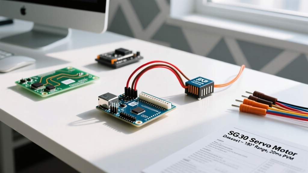

Most introductory tutorials on how to connect servo motor with Arduino boards show a deceptively simple three-wire diagram: brown to GND, red to 5V, and orange to Pin 9. While this might spin a micro SG90 servo for a few seconds on a desk, it completely ignores the electrical realities documented in the component datasheets. When you scale up to high-torque metal-gear servos like the TowerPro MG996R, this naive wiring approach leads to immediate voltage brownouts, ATmega328P microcontroller resets, and potentially permanent damage to your Arduino's onboard voltage regulator.
In this datasheet-driven guide, we bypass the fluff and decode the actual engineering specifications of RC servos. By understanding pulse width modulation (PWM) frequencies, stall currents, and dead band tolerances, you will learn how to design a robust, jitter-free servo power and control circuit that works reliably in real-world 2026 robotics and automation projects.
Decoding the RC Servo Datasheet: What the Specs Actually Mean
Before cutting wires, we must understand the control protocol. RC servos do not use standard analog voltage levels or I2C/SPI communication. They rely on a specific 50Hz PWM signal. According to the Pololu RC Servo Signal Specifications, the position is dictated by the width of the high pulse within a 20-millisecond (ms) window.
| Datasheet Parameter | SG90 (Micro 9g) | MG996R (High-Torque) | Engineering Implication |
|---|---|---|---|
| Operating Voltage | 4.8V - 6.0V | 4.8V - 7.2V | MG996R can handle 2S LiPo (7.4V) via BEC, SG90 will overheat. |
| Stall Current | ~750mA | ~2.5A at 6.0V | Dictates power supply sizing and trace/wire gauge thickness. |
| Pulse Width Range | 500µs - 2400µs | 500µs - 2500µs | Defines the software min/max limits to prevent endpoint stalling. |
| Dead Band Width | 10µs | 5µs | Smaller dead band requires cleaner signal lines to avoid jitter. |
The 5V Pin Fallacy: Analyzing Stall Current
The most common failure mode when makers figure out how to connect servo motor with Arduino setups is relying on the Uno's onboard 5V pin. The Arduino Uno R3 utilizes an NCP1117-5.0 linear voltage regulator. When powered via the barrel jack, this regulator can safely dissipate enough heat to provide roughly 500mA to 800mA of continuous current. When powered via USB, you are limited by the host port's polyfuse (usually 500mA).
Look at the MG996R datasheet: the stall current is 2.5 Amps. When the servo encounters mechanical resistance and stalls, it draws 2.5A. If wired directly to the Arduino's 5V rail, this massive current spike will instantly trigger the Arduino's thermal shutdown or brownout detection (BOD), causing the microcontroller to reboot erratically. Furthermore, the Adafruit Motor Selection Guide explicitly warns against routing high-current inductive loads through logic-level PCB traces to prevent voltage sag and ground bounce.
Step-by-Step Wiring: External Power Supply Integration
To properly interface a high-torque servo, you must separate the logic power from the actuator power while maintaining a common signal reference. Here is the professional wiring protocol:
- Select an External Power Supply: Use a 5V or 6V DC power supply rated for at least 3A per servo. For battery-powered robots, use a dedicated BEC (Battery Eliminator Circuit) or a high-efficiency buck converter (like the LM2596-based modules) stepping down a 2S or 3S LiPo to 6.0V.
- Establish a Common Ground (Critical): Connect the GND of the external power supply directly to the GND pin of the Arduino. Without a shared ground reference, the Arduino's 50Hz PWM signal will float relative to the servo's internal comparator, resulting in violent, unpredictable thrashing.
- Wire the Power Lines: Connect the external 6V VCC to the servo's red wire, and the external GND to the servo's brown/black wire. Use a minimum of 22 AWG silicone wire for these lines to handle the 2.5A stall current without excessive voltage drop.
- Route the Signal Wire: Connect the servo's orange/white signal wire to an Arduino digital pin capable of hardware-backed PWM (e.g., Pin 9 on the Uno). Use 26 AWG wire for the signal line.
- Implement Decoupling Capacitors: Solder a 100µF electrolytic capacitor across the VCC and GND wires as close to the servo connector as possible to absorb transient current spikes. Add a 100nF (0.1µF) ceramic capacitor between the signal wire and GND if your signal wire exceeds 15cm in length to filter high-frequency EMI.
Datasheet-Driven Code: Calibrating Pulse Widths
When using the standard Arduino Servo Library, the default attach(pin) function maps 0° to a 544µs pulse and 180° to a 2400µs pulse. However, datasheets for modern 180-degree servos often specify a wider operational range, typically 500µs to 2500µs.
If you command the servo to 0° using the Arduino defaults, but the servo's internal potentiometer physically stops at 520µs, the motor will continue to push against the mechanical hard stop. This endpoint stalling causes the motor to draw continuous stall current, overheating the coil and burning out the internal wiper potentiometer within minutes.
Expert Troubleshooting Tip: Always use the extended attach function myservo.attach(pin, min, max) to match your specific servo's datasheet. Slowly sweep the min and max values in software until you hear the motor pitch change (indicating a mechanical stall), then back off by 10-20µs to find the true safe electrical endpoints.
#include <Servo.h>

Servo heavyLiftServo;

void setup() {
  // Calibrated to MG996R datasheet limits, minus 10us safety margin
  // to prevent endpoint stalling and potentiometer burnout.
  heavyLiftServo.attach(9, 510, 2490);
}

void loop() {
  heavyLiftServo.write(90); // Center position
  delay(2000);
}
Signal Integrity and the 'Dead Band' Edge Case
The datasheet specifies a 'dead band' (usually 5µs to 10µs). This is the minimum change in pulse width required for the servo's internal error amplifier to command the motor to move. If your Arduino is generating electrical noise, or if long unshielded wires are acting as antennas picking up 50/60Hz mains hum, the pulse width may jitter by 3-4µs. While this is below the dead band threshold, a noisy spike exceeding 5µs will cause the servo to rapidly oscillate back and forth, creating an audible 'buzz' and draining power.
The Fix: If you experience jitter, ensure your Arduino is powered via a clean linear regulator (not a cheap switching buck converter with high ripple), keep the PWM signal wire away from the high-current motor power wires, and verify your common ground connection is thick and secure.
2026 Component BOM & Pricing Estimate
Building a reliable servo interface requires moving beyond basic jumper wires. Below is a recommended Bill of Materials (BOM) for a robust single-servo setup, reflecting 2026 market pricing for quality components.
| Component | Specification | Est. Price (USD) |
|---|---|---|
| Actuator | Genuine TowerPro MG996R (Metal Gear) | $14.50 - $18.00 |
| Power Supply | Mean Well LRS-35-5 (5V 7A Enclosed PSU) | $16.00 |
| Decoupling | Panasonic 100µF 16V Electrolytic + 100nF Ceramic | $0.50 |
| Wiring | 22 AWG Silicone Wire (Red/Black) + 26 AWG Signal | $4.00 |
| Connector | JST-XH 3-Pin Terminal (for secure breadboard/PCB mating) | $0.20 |
Summary
Understanding how to connect servo motor with Arduino hardware requires respecting the physics outlined in the component datasheets. By provisioning an external power supply capable of handling 2.5A stall currents, establishing a rock-solid common ground, filtering EMI with decoupling capacitors, and calibrating your software pulse widths to avoid mechanical endpoint stalling, you transform a jittery, unreliable hobby project into a robust, industrial-grade motion control system.