
Mastering the Arduino Vibration Sensor: The SW-420 Module
Integrating an Arduino vibration sensor into your DIY electronics project opens up a world of possibilities, from knock-activated secret locks to washing machine cycle monitors and industrial equipment fault detection. While there are several ways to detect mechanical shock, the SW-420 vibration sensor module remains the undisputed champion for beginners and hobbyists due to its low cost, digital output, and high sensitivity.
In this comprehensive interfacing tutorial, we will bypass the superficial overview and dive deep into the exact wiring, C++ interrupt-driven code, and real-world hardware filtering required to make your SW-420 module reliable in noisy environments.
Anatomy of the SW-420 Module vs. Bare Sensors
Before wiring anything, it is critical to understand what you are actually connecting. You can buy the bare SW-420 sensor (a small metal cylinder) or the PCB-mounted module. For 95% of Arduino projects, the PCB module is the correct choice.
- The Bare Sensor: Contains a conductive outer sleeve and a flexible inner spring. When vibrated, the spring wiggles and briefly shorts against the outer sleeve, closing the circuit. It requires external pull-up resistors and is highly susceptible to contact bounce.
- The PCB Module: Houses the bare SW-420, but routes its signal through an LM393 dual comparator IC. This chip compares the analog voltage spike of the spring's movement against a reference voltage set by an onboard potentiometer. It outputs a clean, debounced digital HIGH/LOW signal directly compatible with the Arduino's 5V or 3.3V logic pins.
Sensor Comparison Matrix (2026 Market Data)
| Sensor Type | Sensitivity | Output Type | Typical Price (10-pack) | Best Use Case |
|---|---|---|---|---|
| SW-420 Module | High | Digital (LM393) | $4.50 - $7.00 | Knock detection, tamper alarms |
| SW-180 Module | Low/Medium | Digital (LM393) | $5.00 - $8.00 | Washing machine monitoring, heavy shocks |
| Bare Piezo Disc | Variable | Analog (Voltage) | $3.00 - $5.00 | Frequency analysis, acoustic pickups |
Step-by-Step Wiring Guide
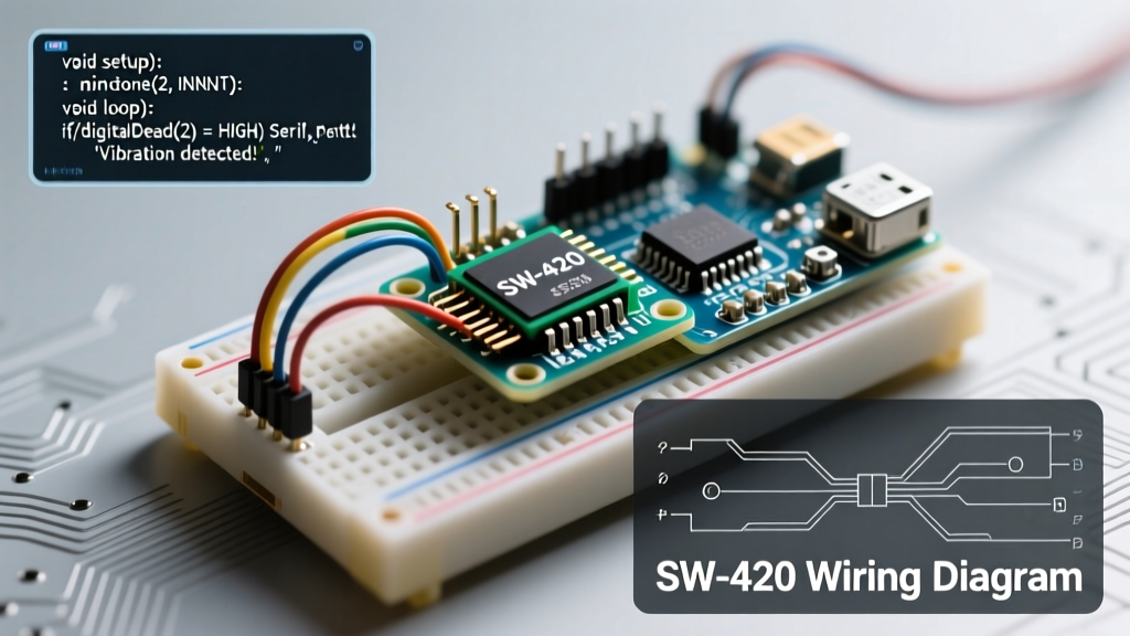
The SW-420 module typically features three or four pins. We will focus on the standard 3-pin digital output configuration (VCC, GND, DO). If your module has an AO (Analog Out) pin, ignore it for this tutorial; the digital comparator output is far more reliable for microcontroller logic.
Required Components
- 1x Arduino Uno R3 (or Nano/ESP32)
- 1x SW-420 Vibration Sensor Module
- Jumper wires (keep them under 15cm to reduce EMI)
- 1x 10kΩ Resistor (for external pull-up, optional but recommended)
- 1x 100nF Ceramic Capacitor (for hardware debouncing)
Pinout Connections
- VCC: Connect to the Arduino
5Vpin. (If using an ESP32, connect to3.3Vto prevent logic level damage). - GND: Connect to the Arduino
GNDpin. - DO (Digital Out): Connect to Arduino
Pin 2. We specifically choose Pin 2 because it supports hardware interrupts on the ATmega328P, which is mandatory for catching millisecond-long vibration pulses.
Pro-Tip: Tuning the Potentiometer
Use a small Phillips screwdriver to adjust the blue trimpot on the module. Turn it clockwise to increase sensitivity (trigger on micro-vibrations) and counter-clockwise to decrease it. Test it by tapping the table; the onboard LED should flicker in response.
Writing the Arduino Code: Why Polling Fails
Most beginner tutorials use digitalRead() inside the loop() to check the sensor state. This is a critical mistake. A physical vibration pulse from the SW-420 spring often lasts only 2 to 10 milliseconds. If your Arduino is busy executing other code (like updating an LCD or sending Wi-Fi data), it will completely miss the pulse.
The professional approach is to use Hardware Interrupts. An interrupt forces the microcontroller to pause its current task, run a quick Interrupt Service Routine (ISR), and then resume. You can read more about this in the official Arduino attachInterrupt() Reference.
Interrupt-Driven C++ Code
// Hardware Interrupt Pin (Pin 2 on Uno/Nano)
const int SENSOR_PIN = 2;
const int LED_PIN = 13;

// Volatile keyword is mandatory for variables modified inside an ISR
volatile bool vibrationDetected = false;
volatile unsigned long lastTriggerTime = 0;

// Debounce window in milliseconds
const unsigned long DEBOUNCE_MS = 50;

void setup() {
  Serial.begin(115200);
  pinMode(LED_PIN, OUTPUT);

  // Use INPUT_PULLUP to ensure the line stays HIGH when idle
  pinMode(SENSOR_PIN, INPUT_PULLUP);

  // Attach interrupt: Trigger on FALLING edge (HIGH to LOW transition)
  attachInterrupt(digitalPinToInterrupt(SENSOR_PIN), vibrationISR, FALLING);

  Serial.println("SW-420 Vibration Sensor Initialized.");
}

void loop() {
  // Check if the ISR flagged a vibration event
  if (vibrationDetected) {
    // Critical section: disable interrupts briefly to read/clear the flag
    noInterrupts();
    vibrationDetected = false;
    interrupts();

    Serial.println("[ALERT] Vibration/Shock Detected!");
    digitalWrite(LED_PIN, HIGH);
    delay(500); // Visual indicator hold time
    digitalWrite(LED_PIN, LOW);
  }

  // Your main code runs here without missing sensor pulses
  // e.g., reading other sensors, updating displays, etc.
}

// Interrupt Service Routine (ISR) - Must be ultra-fast
void vibrationISR() {
  unsigned long currentTime = millis();
  // Software debounce to prevent spring-bounce multiple triggers
  if (currentTime - lastTriggerTime > DEBOUNCE_MS) {
    vibrationDetected = true;
    lastTriggerTime = currentTime;
  }
}
Advanced Troubleshooting & Edge Cases
Even with perfect code, real-world physics will test your circuit. Here are the most common failure modes when deploying an Arduino vibration sensor and how to engineer around them.
1. Contact Bounce and Phantom Triggers
Inside the SW-420, the metal spring physically bounces against the contact wall multiple times before settling. This mechanical phenomenon, known as contact bounce, can register as 5 to 10 distinct vibration events within a single millisecond. While the Arduino Debounce Example covers software debouncing for buttons, the ISR code provided above implements a strict 50ms time-window lockout to solve this specifically for high-frequency shock sensors.
2. Electromagnetic Interference (EMI)
If your SW-420 is mounted near an AC motor, relay, or solenoid, the electromagnetic field can induce a voltage spike in the sensor's wiring, causing false positives. The Hardware Fix: Solder a 100nF ceramic capacitor directly across the VCC and GND pins on the sensor module itself. Additionally, place a 10kΩ pull-up resistor on the DO line and a 100nF capacitor from the DO line to GND. This creates a low-pass RC filter that shunts high-frequency EMI noise to ground while allowing the slower digital edge to pass through to the Arduino. For deeper theory on mechanical switch noise, refer to the SparkFun Switch Basics Tutorial.
3. Ambient Resonance (The HVAC Problem)
Beginners often turn the potentiometer to maximum sensitivity, only to find the sensor triggering randomly. This is usually caused by low-frequency ambient resonance from HVAC systems, passing traffic, or computer cooling fans. The Fix: Mount the sensor using a small piece of double-sided foam tape rather than rigid screws. The foam acts as a mechanical low-pass filter, dampening high-frequency ambient room noise while still transferring sharp, localized shocks (like a knock on the enclosure) directly to the sensor body.
Final Thoughts on Peripheral Integration
The SW-420 is a remarkably capable peripheral when treated with respect for its mechanical limitations. By leveraging hardware interrupts, implementing software debounce lockouts, and applying basic RC filtering for EMI, you transform a $0.50 component into a highly reliable industrial-grade shock detector. Whether you are building a smart home security node or an automated tool-tracking system, mastering this Arduino vibration sensor interface is a foundational skill for any embedded systems engineer.