
Why the MPU6050 is the Ultimate Starting Point
When exploring the intersection of an Arduino and accelerometer sensors, the InvenSense MPU6050 remains the undisputed champion for beginners and hobbyists in 2026. While newer MEMS sensors exist, the MPU6050 offers a built-in Digital Motion Processor (DMP), a highly accessible I2C interface, and a massive repository of community-driven libraries. Whether you are building a self-balancing robot, a gesture-controlled drone, or a simple digital level, understanding how to extract and interpret raw G-force data is a foundational microcontroller skill.
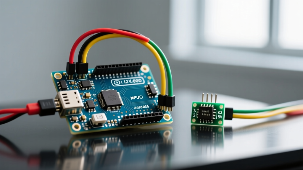
A typical GY-521 breakout board (the most common third-party MPU6050 carrier) costs between $1.50 and $3.50 online, while genuine Adafruit or SparkFun breakouts with integrated voltage regulation and logic level shifting retail around $12.00 to $15.00. This guide focuses on the ubiquitous GY-521 module, highlighting the critical hardware traps that frequently destroy beginner setups.
Hardware Comparison: Choosing Your Sensor
Before wiring, it is crucial to understand why we choose specific accelerometer modules. Here is how the MPU6050 stacks up against other popular I2C/SPI accelerometers available to makers today:
| Sensor Model | Axes | Interface | Best Use Case | Approx. Cost (2026) |
|---|---|---|---|---|
| MPU6050 (GY-521) | 6 (Accel + Gyro) | I2C | General prototyping, tilt, IMU fusion | $1.50 - $3.50 |
| ADXL345 | 3 (Accel only) | I2C / SPI | Tap detection, low-power step counting | $2.00 - $4.00 |
| LIS3DH | 3 (Accel only) | I2C / SPI | Battery-operated wearables, ultra-low power | $4.00 - $6.00 |
| BMI270 | 6 (Accel + Gyro) | I2C / SPI | Advanced robotics, high-precision tracking | $8.00 - $12.00 |
Step-by-Step Wiring: Avoiding the 5V Logic Trap
The most common failure mode when interfacing an Arduino Uno R3 (which operates at 5V logic) with a GY-521 breakout is I2C bus overvoltage. The MPU6050 is strictly a 3.3V device. While the GY-521 board features a tiny LDO voltage regulator to accept 5V on the VCC pin, the SDA and SCL data lines are NOT 5V tolerant. Feeding 5V logic from the Arduino directly into the sensor's I2C pins will degrade the silicon over time, leading to I2C bus lockups and eventual sensor death.
The Proper Wiring Diagram
For a reliable, long-lasting circuit, use a bidirectional logic level converter (like a BSS138-based module, costing roughly $1.20) between your 5V Arduino and the 3.3V sensor.
- VCC (GY-521) to 5V (Arduino) - The onboard LDO will step this down to 3.3V.
- GND (GY-521) to GND (Arduino)
- SDA (GY-521) to LV1 (Level Shifter) → HV1 to A4 (Arduino Uno SDA)
- SCL (GY-521) to LV2 (Level Shifter) → HV2 to A5 (Arduino Uno SCL)
Note: If you are using a native 3.3V board like the Arduino Nano 33 IoT or the ESP32-C3, you can wire SDA and SCL directly without a level shifter.
Pro-Tip on Pull-Up Resistors: The I2C protocol requires pull-up resistors. The GY-521 breakout usually includes 2.2kΩ or 4.7kΩ pull-ups tied to 3.3V. If your I2C bus is unstable and you are using long wires (over 10cm), add external 4.7kΩ pull-up resistors on the 5V side of your level shifter. For deep-dive bus topology rules, refer to the Arduino Wire Library Documentation.
Essential Arduino Code for Raw Data Extraction
While libraries like Adafruit_MPU6050 are excellent, writing bare-metal I2C code using the native Wire.h library teaches you how to read sensor registers directly. This is vital for optimizing loop times in robotics.
Below is a streamlined C++ script to wake the sensor, configure the accelerometer range, and read the raw X, Y, and Z axes.
#include <Wire.h>

const int MPU_ADDR = 0x68; // I2C address (AD0 low)
int16_t AcX, AcY, AcZ;

void setup() {
  Serial.begin(115200);
  Wire.begin();

  // Wake up the MPU-6050
  Wire.beginTransmission(MPU_ADDR);
  Wire.write(0x6B); // PWR_MGMT_1 register
  Wire.write(0);    // Set to zero (wakes up)
  Wire.endTransmission(true);

  // Configure Accelerometer Range (+/- 2g)
  Wire.beginTransmission(MPU_ADDR);
  Wire.write(0x1C); // ACCEL_CONFIG register
  Wire.write(0x00); // AFS_SEL = 0 (+/- 2g)
  Wire.endTransmission(true);
}

void loop() {
  Wire.beginTransmission(MPU_ADDR);
  Wire.write(0x3B); // Starting with register 0x3B (ACCEL_XOUT_H)
  Wire.endTransmission(false);
  Wire.requestFrom(MPU_ADDR, 6, true); // Request 6 registers

  // Read raw 16-bit signed values
  AcX = (Wire.read() << 8) | Wire.read();
  AcY = (Wire.read() << 8) | Wire.read();
  AcZ = (Wire.read() << 8) | Wire.read();

  // Convert to G-force (16384 LSB/g at +/- 2g range)
  float gX = AcX / 16384.0;
  float gY = AcY / 16384.0;
  float gZ = AcZ / 16384.0;

  Serial.print("X: "); Serial.print(gX);
  Serial.print(" | Y: "); Serial.print(gY);
  Serial.print(" | Z: "); Serial.println(gZ);

  delay(50);
}
Understanding the LSB/g Conversion Math
Notice the divisor 16384.0 in the code. According to the TDK InvenSense MPU6050 Datasheet, when the accelerometer is set to the ±2g range (AFS_SEL = 0), the sensitivity scale factor is 16,384 LSB (Least Significant Bits) per G. If you change the register to ±4g, the divisor becomes 8,192. Always match your software divisor to your hardware register configuration, or your physics calculations will be off by a factor of two or four.
Configuring the Digital Low Pass Filter (DLPF)
Raw accelerometer data is notoriously noisy. High-frequency vibrations from motors or environmental hum will cause your Z-axis readings to jitter wildly. The MPU6050 features an onboard Digital Low Pass Filter (DLPF) to mitigate this without burdening your Arduino's CPU.
To set the DLPF, write to register 0x1A (CONFIG). For a beginner building a tilt-sensor or digital spirit level, a bandwidth of 44Hz is ideal. It introduces a slight 4.9ms delay but completely eliminates high-frequency mechanical noise.
// Add this to your setup() function to enable 44Hz Low Pass Filter
Wire.beginTransmission(MPU_ADDR);
Wire.write(0x1A); // CONFIG register
Wire.write(0x03); // DLPF_CFG = 3 (44Hz Accel Bandwidth)
Wire.endTransmission(true);
Troubleshooting Common I2C and Drift Issues
Even with perfect wiring, beginners frequently encounter edge cases when merging an Arduino and accelerometer into a single project. Use this diagnostic matrix to solve them:
1. The Sensor Returns 0 or -1 on the I2C Bus
If an I2C scanner sketch returns no devices, or your code hangs at Wire.endTransmission(), check the AD0 pin. On the GY-521, if AD0 is floating, it usually defaults to LOW (Address 0x68). However, electromagnetic interference can cause it to flip to HIGH (Address 0x69). Fix: Hardwire AD0 to GND with a jumper wire to lock the address to 0x68.
2. Pitch and Roll Angles are Drifting
Accelerometers measure the gravity vector, but they cannot distinguish between gravity and linear acceleration. If your Arduino is mounted on a moving chassis, the vibration will skew your tilt angles. Fix: Implement a Complementary Filter or a Madgwick AHRS algorithm, fusing the accelerometer data with the onboard gyroscope to separate linear motion from gravitational tilt. The Adafruit MPU6050 Guide provides excellent primers on sensor fusion libraries.
3. Z-Axis Reads 0.85g Instead of 1.0g at Rest
Cheap clone GY-521 boards often suffer from poor factory calibration and solder joint stress on the MEMS package, leading to a static offset. Fix: Do not rely on factory defaults. Write a calibration routine in your Arduino's setup() that takes 1000 samples while the sensor is perfectly level, averages them, and stores the X, Y, and Z offsets in the MPU6050's internal offset registers (0x06 to 0x0B).
Next Steps for Your Project
Once you have stable, filtered G-force data streaming to your Arduino, the physical computing possibilities expand dramatically. Try mapping the X and Y tilt angles to a PWM signal to control a servo motor for a camera gimbal, or use the Z-axis impact spike to trigger an interrupt for a digital pedometer. Mastering the raw I2C communication of the MPU6050 ensures you aren't just copying code, but truly engineering robust embedded systems.