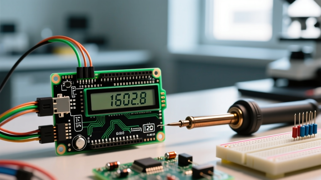

The Precision Standard for 1602A LCD Integration
The 1602A LCD remains one of the most ubiquitous display modules in embedded systems, driven by the legendary Hitachi HD44780 controller. However, a recurring failure point in DIY and prototyping environments is poor display readability, often misdiagnosed as a defective screen. In reality, the issue almost always stems from improper voltage calibration and I2C address mismatches. When configuring your 1602a lcd arduino project, treating the display as a plug-and-play peripheral rather than a calibrated instrument leads to washed-out text, ghosting, or the infamous 'solid black boxes' on the top row.
As of 2026, the majority of 1602A modules shipped from major electronics distributors feature pre-soldered I2C backpacks (typically priced between $3.50 and $5.50 USD). While this saves soldering time, it introduces a new layer of abstraction that masks underlying hardware realities. This guide bypasses basic wiring tutorials and dives deep into the electrical calibration, memory mapping accuracy, and thermal compensation required to achieve pixel-perfect rendering on your 1602A module.
Hardware Anatomy & Voltage Thresholds
Before turning a single potentiometer, you must understand the electrical thresholds of the 1602A. The module operates on a strict 5V logic level, though it can interface with 3.3V microcontrollers (like the ESP32 or Arduino Due) provided you use a bidirectional logic level shifter for the I2C lines (SDA/SCL). According to the 1602A component datasheet, the absolute maximum ratings dictate that VDD must not exceed 7.0V, but optimal logic stability is achieved between 4.5V and 5.5V.
- VSS (Pin 1): Ground (0V). Must share a common ground with your Arduino.
- VDD (Pin 2): Power Supply (5.0V nominal). Drawing approximately 20mA without backlight, and up to 80mA with the LED backlight active.
- V0 (Pin 3): Contrast Control. This is the most critical calibration pin. It requires a variable voltage between 0V and VDD.
- A & K (Pins 15 & 16): Backlight Anode and Cathode. Requires a 5V supply, but must include a current-limiting resistor (typically 10Ω to 22Ω) if not handled by the I2C backpack.
The V0 Contrast Calibration Protocol
The V0 pin controls the voltage bias across the liquid crystal layer. If the voltage is too high (closer to 5V), the crystals do not twist enough, and the screen appears blank. If the voltage is too low (closer to 0V), the crystals over-twist, resulting in dark, bleeding pixels across the entire display.
Step-by-Step Multimeter Calibration
Relying on visual estimation while turning a blue trimpot on an I2C backpack is inaccurate. For precise calibration, use a digital multimeter (DMM) to measure the V0 output relative to VSS (GND).
- Power the Arduino and the 1602A LCD. Ensure the backlight is illuminated so you have a visual reference baseline.
- Set your DMM to DC Voltage mode. Place the black probe on the VSS pin (or Arduino GND) and the red probe on the V0 pin (or the center wiper pin of the trimpot).
- Upload a test sketch that fills both rows with alternating block characters and standard alphanumeric text.
- Adjust the potentiometer while monitoring the DMM. For standard green/blue backlit 1602A modules, the optimal V0 voltage sits precisely between 0.45V and 0.85V.
- Once the text is crisp and the background 'ghosting' of unlit pixels is barely visible, lock the trimpot in place with a dab of clear nail polish or hot glue to prevent mechanical drift from vibrations.
Expert Insight: If your module features a negative temperature coefficient (often found in extended-temperature industrial displays), the optimal V0 voltage will drop by approximately 2mV to 5mV per degree Celsius increase in ambient temperature. Calibrate your V0 at the highest expected operating temperature to prevent black-out conditions in warm environments.
I2C Backpack Address Accuracy: PCF8574 vs. PCF8574A
Modern 1602a lcd arduino setups almost exclusively use an I2C backpack to reduce wiring from 12 pins down to 4 (VCC, GND, SDA, SCL). These backpacks utilize an I/O expander chip—either the NXP PCF8574 or the PCF8574A. Confusing these two chips is the number one cause of 'display not initializing' errors.
According to the official NXP I/O expander datasheet, the two chips have entirely different base I2C address blocks, determined by the state of the A0, A1, and A2 jumper pads on the backpack.
| Expander Chip | Base Address Block | Default Address (A0-A2 High) | Common Alternative (A0 Low) |
|---|---|---|---|
| PCF8574 | 0x20 - 0x27 | 0x27 | 0x26 |
| PCF8574A | 0x38 - 0x3F | 0x3F | 0x3E |
Verifying Address Accuracy via I2C Scanner
Never hardcode 0x27 into your sketch without verification. Manufacturing batches in 2026 frequently swap between PCF8574 and PCF8574A chips depending on silicon supply chains. Use the standard Arduino Wire I2C Scanner sketch to poll the bus. If the serial monitor returns 0x3F, but your LiquidCrystal_I2C library is initialized with 0x27, the display will receive no data, regardless of how perfectly your V0 contrast is calibrated.
Memory Mapping Accuracy: DDRAM vs. CGRAM
Accurate text placement requires an understanding of the HD44780's internal memory architecture. The controller utilizes Display Data RAM (DDRAM) to store character codes. A common calibration error occurs when developers attempt to write to line 2 using standard sequential indexing, only to find the text wrapping to invisible memory addresses.
DDRAM Address Matrix
The 1602A does not map memory linearly from 0 to 31. Instead, it uses a segmented hex address map:
- Line 1: Starts at
0x00and ends at0x0F. - Line 2: Starts at
0x40and ends at0x4F.
If you are writing custom library wrappers or bypassing the standard Arduino LiquidCrystal Library for performance optimization, you must manually set the DDRAM address pointer using the 0x80 command mask. For example, to place the cursor at the exact 5th column of the second row, you must send the command 0x80 | (0x40 + 0x04), which resolves to 0xC4. Failing to account for this hex offset results in data corruption and inaccurate character rendering.
Character Generator RAM (CGRAM) Calibration
For applications requiring custom icons (e.g., battery indicators, thermometers, or proprietary logos), you must calibrate the Character Generator RAM (CGRAM). The HD44780 allows up to 8 custom 5x8 pixel characters. Accuracy here dictates that you map the 8 bytes of pixel data correctly, where the LSB (Least Significant Bit) represents the rightmost pixel. Furthermore, the 8th byte (the bottom row) is often reserved for the cursor blink line. If your custom character appears to have a severed bottom row or triggers an unintended cursor artifact, ensure your 8th byte is masked to 0x00 unless you specifically intend to draw pixels on the lowest scanline.
Troubleshooting Matrix: Symptoms & Calibration Fixes
Use this diagnostic matrix to resolve the most common 1602A accuracy and calibration failures encountered in the field.
| Visual Symptom | Probable Root Cause | Calibration / Hardware Fix |
|---|---|---|
| Solid black boxes on Row 1; Row 2 blank. | V0 voltage is too high (near 5V); LCD is uninitialized. | Adjust V0 trimpot down to ~0.6V. Check EN pin pulse timing. |
| Screen is completely blank; backlight is ON. | I2C address mismatch or missing pull-up resistors. | Run I2C Scanner. Add 4.7kΩ pull-ups to SDA/SCL if using ESP32. |
| Text is visible but heavily ghosted/bled. | V0 voltage is too low (near 0V); over-biasing crystals. | Increase V0 voltage slowly toward 1.0V until ghosting recedes. |
| Characters display as random Japanese/Katakana symbols. | DDRAM pointer corruption or 5V/3.3V logic noise. | Implement logic level shifters; add 100µF decoupling cap on VDD. |
| Display fades out when servo motors engage. | Voltage sag on the 5V rail due to high current draw. | Power servos and LCD from separate 5V regulators; share GND. |
Final Calibration Best Practices
Achieving absolute accuracy with a 1602a lcd arduino setup requires moving beyond basic copy-paste code. By treating the V0 contrast pin as a precise analog threshold, verifying the silicon-specific I2C base addresses, and respecting the non-linear DDRAM memory map, you transform a cheap, washed-out display into a highly reliable, crisp human-machine interface. Always decouple the VDD line with a 100nF ceramic capacitor placed as close to the LCD pins as possible to filter high-frequency noise generated by nearby switching regulators and microcontroller clock cycles.