
The Pin-Starvation Problem in Multi-Sensor Projects
When designing complex environmental monitors, data loggers, or robotics dashboards, integrating Arduino LCD displays alongside multiple sensors is a rite of passage. However, makers frequently hit a wall known as 'pin starvation.' The standard ATmega328P microcontroller found on the Arduino Uno and Nano offers only 14 digital I/O pins. A traditional parallel 16x2 LCD consumes six of those pins (RS, EN, D4, D5, D6, D7), instantly devouring 42% of your available digital real estate. When you need to add an SD card module (4 SPI pins), an RTC, and a BME280 environmental sensor, the math simply stops working.
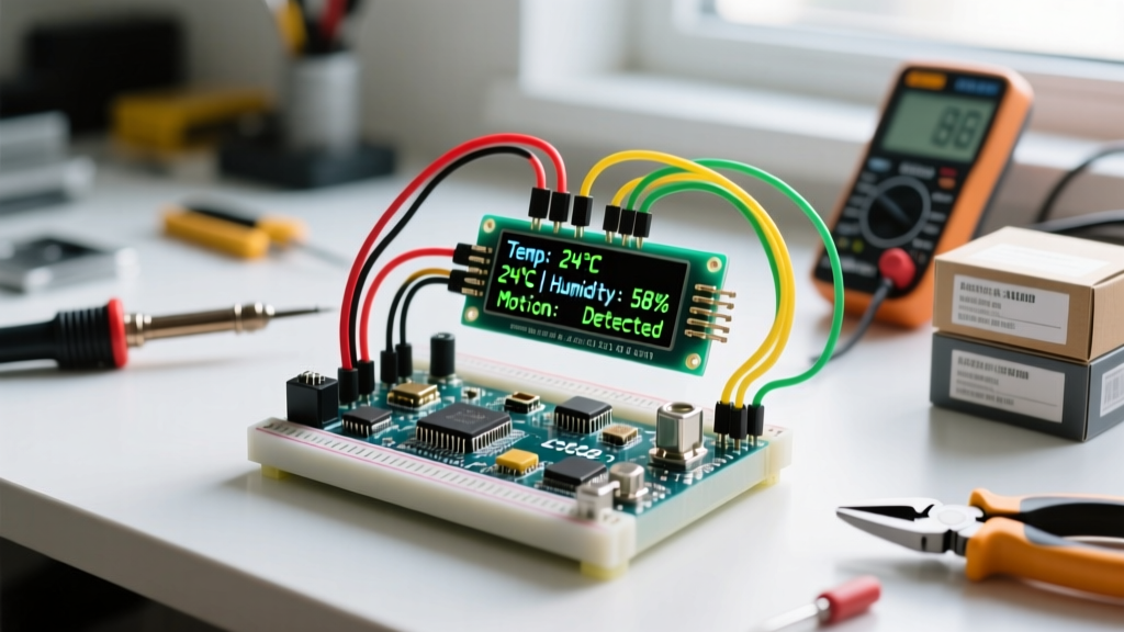
To build robust multi-peripheral setups in 2026, you must move beyond basic parallel wiring and embrace bus-sharing protocols, multiplexing, and strict power budgeting. This guide details exactly how to wire, address, and code Arduino LCD displays in dense sensor networks without causing bus collisions or brownouts.
Hardware Selection Matrix: Choosing the Right Display
Not all displays are created equal when sharing a microcontroller. Selecting the right interface is the first step in preserving I/O pins for your sensors. Below is a comparison of the most common modules used in multi-peripheral rigs.
| Display Type | Controller / Interface | Pins Required | Avg Cost (2026) | Best Multi-Peripheral Use Case |
|---|---|---|---|---|
| 16x2 Parallel | HD44780 / 4-bit Parallel | 6 Digital I/O | $2.50 - $3.50 | Simple rigs with only 1-2 I2C sensors. |
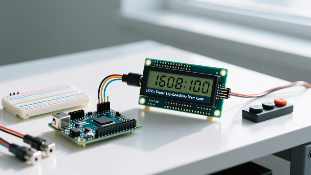
| 16x2 I2C Backpack | PCF8574 / I2C | 2 (SDA, SCL) | $4.00 - $5.50 | Dense sensor networks sharing the I2C bus. |
| 1.8" TFT Color | ST7735 / SPI | 5 (MOSI, SCK, CS, DC, RST) | $9.00 - $12.00 | Graphical data plotting alongside SPI SD cards. |
| 0.96" OLED | SSD1306 / I2C | 2 (SDA, SCL) | $5.00 - $7.00 | Compact dashboards requiring high refresh rates. |
Pro Tip: For multi-sensor setups, the 16x2 I2C backpack is the undisputed workhorse. It shifts the parallel data requirements to the PCF8574 I/O expander chip, freeing your microcontroller's pins for hardware interrupts and SPI peripherals.
Mastering I2C Address Collisions
The most common failure mode in multi-peripheral setups is an I2C address collision. The I2C bus allows up to 128 devices, but each must have a unique 7-bit address. Standard Arduino LCD displays with a PCF8574 backpack typically ship with an address of 0x27 or 0x3F.
But what happens when you add an MPU6050 accelerometer (0x68) and a DS3231 Real Time Clock (also 0x68)? The bus locks up, and your LCD will freeze or display garbage characters.
Step 1: Map Your Bus
Before wiring your sensors permanently, run an I2C scanner sketch. The Adafruit I2C Address List is an invaluable resource for cross-referencing default sensor addresses. Connect all peripherals and verify that no two devices share a hex address.
Step 2: Resolve Collisions
If you discover a collision, you have three hardware-level solutions:
- Address Jumper Pads: Many PCF8574 backpacks and sensor breakout boards (like the BME280) feature A0, A1, or SDO pads. Soldering these pads shifts the I2C address to an alternative slot.
- Software Reconfiguration: Some sensors allow you to change their address via an initialization command in your setup loop, though this is rare for passive displays.
- I2C Multiplexing (The Ultimate Fix): If you are stuck with fixed-address sensors, introduce a TCA9548A I2C Multiplexer (~$3.50). This chip sits on the main I2C bus and provides 8 independent downstream channels. You can place your Arduino LCD display on Channel 1, and your conflicting RTC/IMU sensors on Channel 2, completely isolating the traffic.
Power Budgeting: Avoiding Brownouts and Bus Lockups
When wiring multiple peripherals, makers often ignore the current limits of the Arduino's onboard voltage regulator. An I2C LCD backlight draws between 50mA and 120mA. An SD card module can spike to 200mA during write operations. A string of sensors adds another 30mA.
Hardware Warning: The standard Arduino Nano relies on a Schottky diode from the USB 5V line, which is rated for roughly 500mA. The Arduino Uno's NCP1117 linear regulator must dissipate excess voltage as heat. If you power a Uno via the barrel jack at 9V, and your LCD + Sensors draw 300mA, the regulator must dissipate (9V - 5V) * 0.3A = 1.2 Watts. This will trigger the onboard thermal shutdown, causing the microcontroller to reset randomly and corrupting your sensor data.
The External Buck Converter Solution
For any multi-peripheral setup exceeding 200mA total draw, bypass the onboard regulator entirely. Use an LM2596 buck converter module ($2.00) connected to your main power supply. Set the potentiometer to output exactly 5.05V, and wire this directly to the 5V pin on the Arduino header (bypassing the USB diode and linear regulator). This provides a clean, high-current rail for your Arduino LCD displays and sensor arrays.
Code Architecture: Non-Blocking Display Updates
In a multi-sensor environment, timing is everything. Writing data to an I2C LCD is relatively slow. Sending a full 32-character update over a 100kHz I2C bus takes roughly 3 to 5 milliseconds. If you use delay() to pace your display updates, you will block the microcontroller from polling time-sensitive sensors or catching hardware interrupts from a flow meter or anemometer.
According to the official Arduino timing documentation, utilizing millis() is mandatory for responsive peripheral management.
Implementing a Display State Machine
Instead of updating the screen every loop iteration, separate your sensor polling from your display rendering. Poll sensors continuously, store the data in variables, and only push to the LCD every 250ms.
unsigned long lastDisplayUpdate = 0;
const long displayInterval = 250; // Update LCD 4 times a second

void loop() {
  // 1. Poll sensors continuously (non-blocking)
  float temp = bme.readTemperature();
  float humidity = bme.readHumidity();

  // 2. Handle time-critical interrupts
  checkFlowMeterInterrupts();

  // 3. Update LCD only when interval has passed
  unsigned long currentMillis = millis();
  if (currentMillis - lastDisplayUpdate >= displayInterval) {
    lastDisplayUpdate = currentMillis;
    lcd.setCursor(0, 0);
    lcd.print("Temp: "); lcd.print(temp);
    lcd.setCursor(0, 1);
    lcd.print("Hum: "); lcd.print(humidity);
  }
}
This architecture ensures that a slow I2C LCD write never delays the reading of a fast-changing sensor.
Real-World Troubleshooting Matrix
When integrating Arduino LCD displays with motors, relays, or long sensor cables, electromagnetic interference (EMI) and bus capacitance cause bizarre behaviors. Use this matrix to diagnose complex rig failures.
| Symptom | Root Cause | Hardware / Software Fix |
|---|---|---|
| LCD freezes when relay triggers | EMI spike collapsing the I2C SDA/SCL logic levels. | Route I2C wires away from relay coils. Add a 100nF decoupling capacitor directly across the LCD VCC/GND pins. |
| Garbage characters on boot | LCD initializes before microcontroller I2C bus is stable. | Add a 500ms delay() in setup() before calling lcd.init(), or implement a software I2C bus reset sequence. |
| Display dims when SD card writes | Voltage sag on the 5V rail due to SD card current spike. | Add a 470µF electrolytic capacitor on the main 5V bus to supply transient current demands. |
| Intermittent I2C NACK errors | Bus capacitance too high from long sensor wires. | Reduce I2C clock speed to 50kHz using Wire.setClock(50000); or add 2.2kΩ external pull-up resistors to SDA/SCL. |
Conclusion
Integrating Arduino LCD displays into multi-peripheral setups requires shifting your mindset from simple component wiring to holistic system architecture. By leveraging I2C backpacks to save pins, utilizing multiplexers to resolve address conflicts, engineering a robust external power rail, and writing non-blocking code, you can build professional-grade sensor dashboards that run reliably 24/7. Always map your I2C addresses and budget your milliamps before soldering your final prototype.