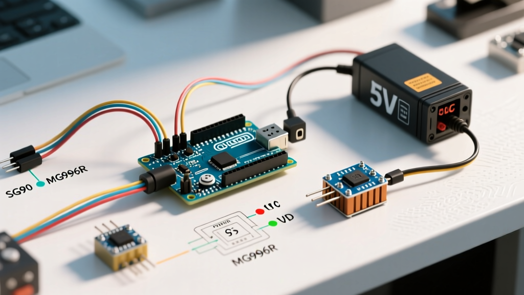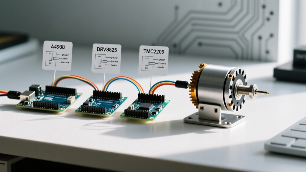

When makers and engineers ask how to use a stepper motor with Arduino, the answer rarely stops at basic wiring diagrams. The true challenge lies in matching the motor's inductance and phase current requirements to the appropriate driver IC. In 2026, the landscape of stepper drivers has shifted dramatically. Legacy chips like the Allegro A4988 are being phased out in favor of ultra-quiet, UART-configurable silicon like the Trinamic TMC2209. This guide provides a rigorous component comparison and a definitive wiring methodology for integrating NEMA 17 and NEMA 23 stepper motors with Arduino microcontrollers.
Selecting the Stepper Motor: NEMA 17 vs. NEMA 23
Before wiring, you must select the correct physical form factor based on your torque requirements. The NEMA 17 (42mm faceplate) remains the undisputed king of desktop CNCs, 3D printers, and camera sliders. A standard workhorse like the StepperOnline 17HS19-2004S1 delivers 59 N·cm (84 oz-in) of holding torque at 1.68A per phase. Priced around $13 to $16 in 2026, it offers the best torque-to-cost ratio for sub-50W applications.
If your project requires moving heavy gantries or high-inertia loads, step up to a NEMA 23 (57mm faceplate). However, NEMA 23 motors often demand 3A+ per phase, instantly disqualifying standard Arduino shield-mounted drivers and requiring external buck converters and high-current choppers like the TB6600.
2026 Stepper Driver Comparison Matrix
Choosing the right driver dictates your system's acoustic profile, thermal ceiling, and microstepping resolution. Below is a technical comparison of the four most prevalent driver ICs used with Arduino boards today.
| Driver IC | Max Current (RMS) | Microstepping | Acoustic Profile | Avg Price (2026) |
|---|---|---|---|---|
| A4988 | 1.5A (w/ cooling) | 1/16 | Loud / Whining | $2 - $4 |
| DRV8825 | 2.0A (w/ cooling) | 1/32 | Moderate | $3 - $5 |
| TMC2209 | 2.0A | 1/256 | Silent (StealthChop2) | $6 - $9 |
| TB6600 | 4.0A (External) | 1/32 | Moderate | $12 - $18 |
Step-by-Step: How to Use a Stepper Motor with Arduino
For this guide, we will focus on the TMC2209 in step/dir mode, as it represents the modern standard for precision and low acoustic emission in DIY robotics.
The Decoupling Capacitor Rule
The most common cause of instant driver death is inductive voltage kickback. You must solder or wire a 100µF electrolytic capacitor directly across the VMOT and GND pins on the driver carrier board. This absorbs voltage spikes when the motor coils are rapidly energized and de-energized, protecting the internal MOSFETs.
Wiring the Control Pins
- EN (Enable): Connect to Arduino GND to keep the driver permanently enabled, or to a digital pin for software-controlled freewheeling.
- STEP: Connect to an Arduino hardware interrupt pin (e.g., Pin 2 or 3 on an Uno) for precise timing without blocking the main loop.
- DIR: Connect to any standard digital I/O pin.
- VMOT: Connect to your main power supply (8V to 29V for the TMC2209).
- GND: Connect to the shared ground of your power supply and Arduino.
Identifying Coil Pairs Without a Datasheet
Stepper motors feature four wires representing two distinct electromagnetic coils (A and B). If you lack the manufacturer pinout, use a digital multimeter set to continuity mode. Probe the wires in pairs. When you find two wires that show a low resistance (typically 1 to 5 ohms) or trigger the continuity beep, you have found one coil pair. The remaining two wires form the second pair. Connect one pair to the A (1A, 1B) terminals and the other to the B (2A, 2B) terminals. Reversing the polarity of a single coil will simply reverse the motor's direction, which can be easily corrected in your Arduino sketch.
VREF Calibration: The Mathematical Approach
For drivers relying on a physical potentiometer (like the DRV8825 or A4988), guessing the current limit leads to overheated motors or skipped steps. You must calculate the reference voltage (VREF).
According to the Texas Instruments DRV8825 documentation, the formula is:
Current Limit = VREF × 2
Therefore, if your NEMA 17 motor is rated for 1.5A per phase:
VREF = 1.5A / 2 = 0.75V
Use a multimeter to measure the voltage between the GND pin and the metal body of the potentiometer while adjusting it with a ceramic screwdriver. Never use a metal screwdriver, as it can short the potentiometer to nearby components.
Step/Dir vs. UART Configuration on the TMC2209
While Step/Dir is the easiest way to learn how to use a stepper motor with Arduino, the TMC2209 unlocks its full potential via UART (Universal Asynchronous Receiver-Transmitter). By connecting the driver's TX/RX pins to the Arduino's SoftwareSerial pins (with a 1kΩ resistor in line with the RX pin to prevent logic level conflicts), you can dynamically adjust the motor current on the fly.
UART configuration allows you to enable CoolStep, which dynamically scales the current based on the mechanical load, reducing power consumption by up to 75% during low-load movements. For deep-dive integration, the RepRap Wiki Stepper Driver Documentation offers excellent register maps for Trinamic ICs.
Acceleration Profiling with AccelStepper
Sending raw HIGH/LOW pulses to the STEP pin at a constant high speed will cause the motor to stall due to rotor inertia. You must use acceleration profiling. The Adafruit Motor Selection Guide highly recommends trapezoidal motion profiles for high-torque applications.
Using the AccelStepper library, configure your parameters based on your mechanical lead screw or belt ratio:
setMaxSpeed(1000): Sets the absolute ceiling in steps per second.setAcceleration(500): Dictates how fast the motor ramps up. A value too high will cause the motor to hum and stall; a value too low will make the machine lethargic.
Real-World Failure Modes & Edge Cases
Mid-Band Resonance
Stepper motors suffer from a phenomenon called mid-band resonance, typically occurring between 1,000 and 2,000 RPM (depending on microstepping). The rotor overshoots the magnetic field, causing violent vibration and stalled steps. Mitigation strategies include implementing 1/16 microstepping or higher, or using software to rapidly accelerate through the resonant frequency band.
Thermal Shutdown Hysteresis
If your driver gets too hot, it will trigger internal thermal shutdown (usually around 150°C junction temperature). The motor will stop, the driver will cool, and then it will restart, creating a stuttering effect. If this occurs, attach a heatsink with thermal adhesive, increase microstepping to reduce RMS current, or switch to a driver with a higher efficiency rating.
Electromagnetic Interference (EMI)
When designing enclosures or custom PCBs for your Arduino and stepper driver, adhere to IPC-2221 standards for trace clearance. Always route high-current motor wires away from low-voltage logic lines. Unshielded stepper cables acting as antennas can induce voltage spikes in the STEP/DIR lines, causing the Arduino to register phantom steps and lose positional accuracy.
Final Verdict
Understanding how to use a stepper motor with Arduino requires moving beyond basic tutorials. For quiet, high-precision desktop applications in 2026, the TMC2209 paired with a 1.5A NEMA 17 motor is the undisputed champion. For heavy-duty, high-current gantry systems, pair a NEMA 23 with a TB6600 external driver. Always respect the decoupling capacitor rule, calculate your VREF mathematically, and utilize acceleration libraries to ensure reliable, skip-free motion.