
The Anatomy of Arduino and Servo Motor Integration
Integrating an Arduino and servo motor is a foundational skill in robotics, RC prototyping, and automated manufacturing. Unlike standard DC motors that spin freely, hobby servos utilize a closed-loop feedback system. Inside the casing, a potentiometer continuously reads the output shaft's physical position, while an internal H-bridge circuit adjusts the motor's direction and speed to match the incoming Pulse Width Modulation (PWM) signal. In 2026, while digital signal processing inside modern servos has vastly improved holding torque and response times, the fundamental 50Hz PWM control protocol established decades ago remains the industry standard for microcontroller interfacing.
This guide bypasses generic "sweep" tutorials to provide electrical engineers and advanced makers with precise wiring topologies, microsecond-level calibration code, and thermal management strategies required for reliable, real-world deployments.
2026 Servo Hardware Matrix: Selecting the Right Actuator
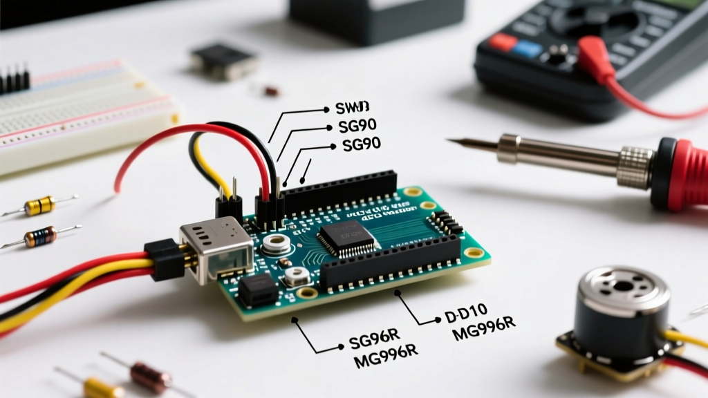
Choosing the correct servo dictates your power supply architecture. A common point of failure is attempting to drive high-torque metal-gear servos directly from an Arduino's onboard linear regulator. Below is a comparison of the three most prevalent actuator classes used in MCU peripherals today.
| Model | Type | Stall Torque | Stall Current | Op. Voltage | Est. Price (2026) |
|---|---|---|---|---|---|
| TowerPro SG90 | Analog / Plastic | 1.8 kg-cm | ~220 mA | 4.8V - 6.0V | $2.50 - $4.00 |
| TowerPro MG996R | Analog / Metal | 13.0 kg-cm | ~2.50 A | 4.8V - 7.2V | $8.00 - $12.00 |
| DS3218 (270°) | Digital / Metal | 20.0 kg-cm | ~3.20 A | 5.0V - 8.4V | $15.00 - $19.00 |
As highlighted by the Adafruit Motor Selection Guide, the stall current is the critical metric for power supply sizing. An Arduino Uno R3's onboard 5V regulator (typically an NCP1117) can safely supply roughly 400mA to 800mA depending on thermal conditions. While a single SG90 can technically be powered from the 5V pin, an MG996R pulling 2.5A will instantly trigger the Arduino's thermal shutdown or drop the logic voltage, causing erratic MCU resets.
Critical Wiring Topologies & The Common Ground Mandate
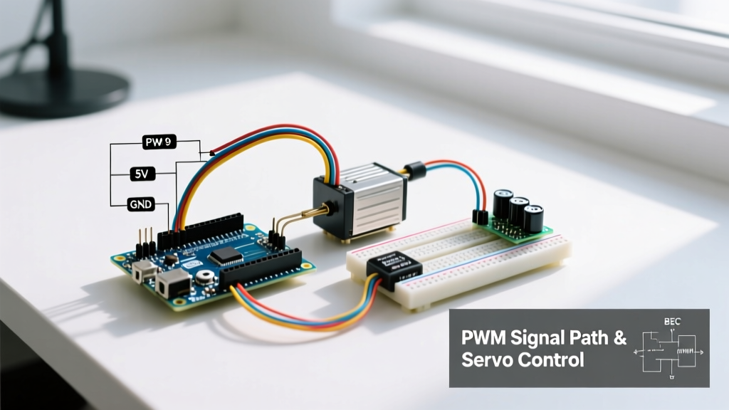
When wiring an Arduino and servo motor, the physical connections are straightforward, but the power delivery network requires strict adherence to electrical best practices.
1. The Common Ground Rule
The PWM signal generated by the Arduino's ATmega328P or ESP32 is a voltage differential referenced to the microcontroller's ground. If your servo is powered by an external battery pack or Buck converter, the ground of the external power supply must be tied directly to the Arduino's GND pin. Without this shared reference plane, the PWM signal will float, resulting in violent servo jitter or complete failure to respond.
2. External Power and Capacitor Smoothing
For any setup utilizing MG996R or DS3218 servos, use a dedicated 5V to 6V power supply. A 5A switching power supply or a dedicated RC BEC (Battery Eliminator Circuit) is mandatory. Furthermore, servos draw current in sharp, high-frequency spikes during direction reversals. To prevent voltage sag from resetting your microcontroller, solder a 470µF to 1000µF electrolytic capacitor across the VCC and GND rails as close to the servo connector as physically possible.
Pro-Tip: Never route servo power traces through breadboards. Standard breadboard clips are rated for roughly 1A to 2A continuous current. A stalled MG996R will melt the internal copper clips, creating a high-resistance joint that exacerbates voltage drop and generates localized heat. Use direct solder joints or XT60 connectors for the power rails.
Precision Code: Calibrating Microsecond Pulse Widths
The standard Arduino <Servo.h> library maps the write(0) to write(180) commands to a hardcoded 544 to 2400 microsecond pulse width. However, manufacturing tolerances mean that a physical 0° on an SG90 might actually occur at 600µs, and 180° at 2350µs. Forcing the library's default extremes often pushes the internal potentiometer past its physical limits, causing the motor to continuously stall, draw maximum current, and strip the nylon gears.
According to the official Arduino Servo Library Documentation, you can override these limits during the attach() function, or better yet, use writeMicroseconds() for absolute precision.
Calibration Sketch
Upload this diagnostic sketch to map the exact physical boundaries of your specific servo. Use the Serial Monitor to input microsecond values, starting safely at 1000µs and incrementing by 50µs.
#include <Servo.h>

Servo precisionServo;
const int servoPin = 9; // Must be a PWM-capable pin

void setup() {
  Serial.begin(115200);
  // Attach without overriding default min/max limits yet
  precisionServo.attach(servoPin);
  Serial.println("Enter microseconds (e.g., 1500):");
}

void loop() {
  if (Serial.available() > 0) {
    int us = Serial.parseInt();

    // Safety bounds to prevent immediate gear destruction
    if (us >= 500 && us <= 2500) {
      precisionServo.writeMicroseconds(us);
      Serial.print("Pulse set to: ");
      Serial.print(us);
      Serial.println("us");
    } else {
      Serial.println("Value out of safe bounds (500-2500).");
    }
  }
}
Once you identify the exact microsecond values where the servo reaches its mechanical stops without buzzing, record them. You can then pass these exact values into your production code's attach function: precisionServo.attach(9, 620, 2380);. This guarantees the software never commands a position outside the hardware's physical capabilities.
Real-World Failure Modes & Troubleshooting
Even with perfect wiring, environmental and mechanical factors can disrupt closed-loop control. Here is how to diagnose the most common anomalies encountered in the field.
- High-Frequency Jitter at Rest: If the servo vibrates slightly while holding a position, the issue is rarely the code. It is almost always power supply noise or an inadequate ground connection. Ensure your logic ground and power ground are bonded at a single star-point. If using long wire runs (>15cm), the inductance of the wire can cause voltage reflections; add a 0.1µF ceramic capacitor in parallel with your bulk electrolytic capacitor directly at the servo pins.
- Thermal Overload & Shutdown: Analog servos like the MG996R will draw stall current continuously if the mechanical load exceeds their torque rating. The internal H-bridge MOSFETs will rapidly overheat. If your application requires holding a heavy static load, switch to a digital servo (like the DS3218) which utilizes PID control to apply short, high-current bursts rather than continuous DC current, vastly improving thermal efficiency.
- Erratic Sweeping on MCU Boot: When an Arduino powers on or resets, its GPIO pins float before the
setup()loop initializes the PWM timers. This floating state can be interpreted by the servo as random PWM noise, causing it to violently snap to an unknown position. To fix this, wire a 10kΩ pull-down resistor between the PWM signal pin and GND to hold the line LOW during boot sequences, or use a logic-level MOSFET to disable the servo's power rail until the MCU is fully initialized.
Summary of Best Practices
Successfully deploying an Arduino and servo motor requires treating the actuator not just as a peripheral, but as a high-current inductive load. By utilizing external power supplies, enforcing common ground topologies, and calibrating microsecond pulse boundaries via the Serial Monitor, you eliminate 95% of the hardware failures that plague beginner robotics projects. For further reading on inductive load management, the Pololu RC Servo Guide offers excellent schematics on integrating flyback diodes and optoisolators for industrial-grade MCU isolation.