
The Core Challenge: Logic Level vs. High Power
Integrating environmental sensors with high-power loads is a foundational skill in embedded systems. While microcontrollers like the Arduino Uno R3 excel at reading 3.3V or 5V logic signals from peripherals, they cannot directly drive mains-powered lighting, heavy DC motors, or solenoid valves. The bridge between low-voltage sensor logic and high-voltage actuation is the electromechanical relay. In this guide, we will explore the exact methodology for building a robust 5V relay Arduino circuit triggered by a passive infrared (PIR) motion sensor, complete with hardware protection and fail-safe software architecture.
Anatomy of the SRD-05VDC-SL-C 5V Relay Module
The ubiquitous blue 1-channel relay module found in most maker kits is built around the Songle SRD-05VDC-SL-C. Understanding its internal architecture is critical for preventing catastrophic failure in your sensor integration projects.
- Coil Specifications: The internal electromagnet has a coil resistance of approximately 70Ω. At 5V, it draws roughly 71mA of current. This exceeds the safe continuous current limit of a standard Arduino I/O pin, necessitating a driver transistor (usually an S8050 or 2N2222) on the module's PCB.
- Contact Ratings: Rated for 10A at 250VAC or 15A at 125VAC. However, for inductive loads like motors, you must derate this capacity by at least 50% to prevent contact welding.
- Optocoupler Isolation: High-quality modules include a PC817 optocoupler. This component uses light to transmit the trigger signal, providing galvanic isolation between your Arduino's sensitive 5V logic rail and the relay's noisy inductive coil circuit.
Active High vs. Active Low Triggering
A common pitfall in 5V relay Arduino integrations is misunderstanding the trigger logic. Most commercial modules feature a jumper cap labeled High/Low. When set to Low, the relay activates when the signal pin is pulled to GND (0V). When set to High, it activates at 5V. For noise immunity in sensor applications, Active Low is generally preferred, as it keeps the default state pulled high, resisting spurious electromagnetic interference (EMI).
Bill of Materials & 2026 Component Pricing
Building a reliable sensor-triggered relay circuit requires specific components. Below is a realistic breakdown of 2026 market pricing for high-quality, genuine parts.
| Component | Model / Specification | Estimated Cost (2026) | Role in Circuit |
|---|---|---|---|
| Microcontroller | Arduino Uno R3 (or R4 Minima) | $24.00 - $28.00 | Logic processing & sensor polling |
| Relay Module | 1-Channel 5V with PC817 Optocoupler | $2.50 - $4.00 | Galvanic isolation & load switching |
| Sensor | HC-SR501 PIR Motion Sensor | $1.80 - $3.00 | Environmental stimulus detection |
| Power Supply | 5V 2A USB-C Buck Converter | $5.00 - $7.50 | Isolated power for relay coil |
| Protection Diode | 1N4007 (if not pre-soldered) | $0.10 | Back-EMF suppression |
Step-by-Step Sensor Integration Wiring
For this tutorial, we are integrating an HC-SR501 PIR motion sensor to trigger a 5V relay that controls a 120VAC desk lamp. The HC-SR501 outputs a clean 3.3V to 5V HIGH signal when motion is detected, making it perfectly compatible with the Arduino's digital input pins.
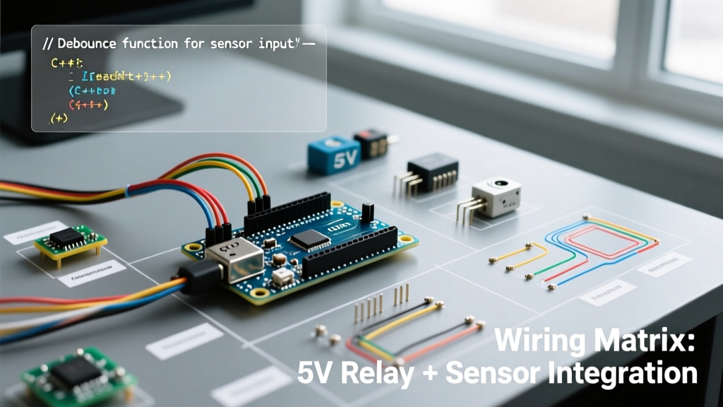
Pinout Matrix
| Module / Sensor | Pin | Connects To | Wire Color Recommendation |
|---|---|---|---|
| HC-SR501 PIR | VCC | Arduino 5V Pin | Red |
| HC-SR501 PIR | OUT | Arduino Digital Pin 2 | Yellow |
| HC-SR501 PIR | GND | Arduino GND | Black |
| 5V Relay Module | VCC | External 5V Supply (+) | Orange |
| 5V Relay Module | GND | External 5V Supply (-) & Arduino GND | Purple |
| 5V Relay Module | IN (Signal) | Arduino Digital Pin 8 | Green |
Expert Warning: Never power the relay module's VCC directly from the Arduino's onboard 5V regulator if you are also powering the board via USB. The USB port typically limits current to 500mA. The relay coil pull-in surge combined with the PIR sensor can cause a voltage sag, resulting in spontaneous Arduino resets. Always use a dedicated external 5V power supply for the relay coil, tying only the GND lines together to establish a common reference.
Robust Arduino C++ Code with Safety Timeouts
When dealing with high-voltage loads, software must include fail-safes. If the microcontroller freezes or the PIR sensor gets stuck in a HIGH state due to thermal interference, the relay should not remain engaged indefinitely. The code below implements a strict safety timeout.
#include <Arduino.h>

// Pin Definitions
const int PIR_PIN = 2;
const int RELAY_PIN = 8;

// Timing & State Variables
unsigned long lastTriggerTime = 0;
const unsigned long SAFETY_TIMEOUT = 300000; // 5 minutes max ON time
const unsigned long DEBOUNCE_DELAY = 500;    // 500ms sensor debounce
bool isRelayActive = false;

void setup() {
  Serial.begin(115200);
  pinMode(PIR_PIN, INPUT);

  // Configure relay pin as output and set to HIGH (Active LOW module default)
  pinMode(RELAY_PIN, OUTPUT);
  digitalWrite(RELAY_PIN, HIGH);

  // Allow PIR sensor 30 seconds to calibrate its internal baseline
  Serial.println("Calibrating PIR Sensor... Do not move.");
  delay(30000);
  Serial.println("System Ready.");
}

void loop() {
  bool motionDetected = digitalRead(PIR_PIN);
  unsigned long currentMillis = millis();

  // Trigger Logic with Debounce
  if (motionDetected == HIGH && (currentMillis - lastTriggerTime > DEBOUNCE_DELAY)) {
    lastTriggerTime = currentMillis;
    if (!isRelayActive) {
      digitalWrite(RELAY_PIN, LOW); // Activate Relay (Active LOW)
      isRelayActive = true;
      Serial.println("Motion Detected: Relay ENGAGED.");
    }
  }

  // Timeout & Auto-Shutoff Logic
  if (isRelayActive) {
    if (motionDetected == LOW && (currentMillis - lastTriggerTime > 10000)) {
      // Turn off if no motion for 10 seconds
      digitalWrite(RELAY_PIN, HIGH);
      isRelayActive = false;
      Serial.println("Area Clear: Relay DISENGAGED.");
    } else if (currentMillis - lastTriggerTime > SAFETY_TIMEOUT) {
      // Hard safety timeout override
      digitalWrite(RELAY_PIN, HIGH);
      isRelayActive = false;
      Serial.println("WARNING: Safety Timeout Reached. Relay FORCED OFF.");
    }
  }
}
Real-World Failure Modes & Troubleshooting
Even with perfect wiring, 5V relay Arduino integrations frequently fail in the field. Here is how to diagnose the most common edge cases using a digital multimeter (DMM).
1. The "Click-Reset" Brownout Loop
Symptom: The Arduino serial monitor reconnects, and the relay clicks rapidly every few seconds.
Root Cause: The inductive kickback from the relay coil collapsing is feeding noise back into the 5V rail, or the coil draw is sagging the voltage below the ATmega328P's brown-out detection threshold (typically 4.3V).
Solution: Verify the flyback diode (1N4148 or 1N4007) is soldered in reverse bias across the relay coil pins on the PCB. If missing, add one. Ensure the external 5V power supply can deliver at least 1A peak current.
2. PIR Sensor False Triggers
Symptom: The relay activates randomly when no one is in the room.
Root Cause: The HC-SR501 is highly susceptible to RF interference and thermal drafts. The relay's own switching arc can generate enough EMI to fool the PIR's op-amp.
Solution: Physically separate the PIR sensor from the relay module by at least 15cm. Add a 0.1µF ceramic decoupling capacitor directly across the VCC and GND pins of the PIR sensor to filter high-frequency noise.
3. Optocoupler CTR Degradation
Symptom: The Arduino outputs 5V, but the relay fails to engage after months of operation.
Root Cause: The Current Transfer Ratio (CTR) of cheap PC817 optocouplers degrades over time, especially in high-temperature environments. The Arduino I/O pin cannot sink enough current to illuminate the internal LED sufficiently.
Solution: According to the official Arduino Uno R3 documentation, an I/O pin can safely source/sink up to 20mA continuously. Ensure your optocoupler's series resistor is sized to draw no more than 15mA, and replace the module with one featuring a high-CTR optocoupler or a dedicated MOSFET driver if operating in harsh environments.
Safety Standards for Mains Voltage Switching
Integrating a 5V relay with an Arduino to switch 120VAC or 240VAC mains voltage introduces severe life-safety risks. The cheap green relay modules commonly sold online lack adequate creepage and clearance distances on the PCB to safely isolate mains voltage from low-voltage logic over long periods, especially in humid environments.
When designing permanent installations, adherence to NFPA codes and standards (which govern the National Electrical Code) is mandatory. You must ensure that all mains-voltage wiring is housed in grounded, fire-retardant enclosures (like ABS or polycarbonate junction boxes) and that wire gauges match the load requirements. For commercial or workplace sensor integrations, always consult OSHA's electrical safety guidelines to ensure compliance with lockout/tagout procedures and proper grounding techniques. Never prototype mains AC circuits on a breadboard; use terminal blocks and proper strain relief.