
The Anatomy of a Classic Memory Game
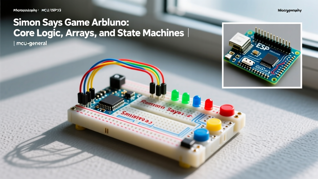
Building a Simon Says game Arduino project is a foundational rite of passage for embedded systems hobbyists. On the surface, it appears to be a simple exercise in blinking LEDs and reading pushbuttons. However, under the hood, a robust implementation requires a solid grasp of pseudo-random number generation (PRNG), dynamic array management, hardware debouncing, and non-blocking Finite State Machines (FSM). In 2026, with the widespread adoption of the Arduino Uno R4 Minima and its 48MHz Cortex-M4 processor, makers have more computational headroom than ever, but the core architectural concepts remain unchanged. This guide deconstructs the underlying logic required to build a professional-grade memory game, moving beyond copy-paste code to explain the 'why' and 'how' of embedded game design.
Hardware Foundation: Component Selection and 2026 Pricing
Before diving into the firmware, we must define the physical interface. A standard four-button setup requires careful component selection to ensure tactile feedback and reliable electrical signaling. Below is a recommended bill of materials (BOM) optimized for a modern Uno R4 Minima build.
| Component | Specification | Qty | Est. Cost (2026) |
|---|---|---|---|
| Microcontroller | Arduino Uno R4 Minima (Cortex-M4) | 1 | $27.50 |
| Tactile Switches | 12x12mm, 260gf actuation force | 4 | $0.60 |
| LEDs | 5mm Diffused (Red, Green, Blue, Yellow) | 4 | $0.40 |
| Current Limiting Resistors | 220Ω Carbon Film (1/4W) | 4 | $0.10 |
| Audio Transducer | 27mm Passive Piezo Disc | 1 | $1.20 |
| Debounce Capacitors | 100nF Ceramic (X7R) | 4 | $0.20 |
Using a passive piezo disc rather than an active buzzer is critical. Active buzzers have internal oscillators and can only produce a single frequency. A passive piezo relies on the microcontroller's PWM (Pulse Width Modulation) timers to generate specific square wave frequencies, allowing you to map distinct musical notes (e.g., C4, E4, G4, C5) to each color button.
Concept 1: Pseudo-Randomness and the Floating Pin Trick
Microcontrollers are deterministic machines; they do not inherently understand 'randomness.' If you call the random(0, 4) function immediately after booting an Arduino without seeding the generator, it will output the exact same sequence of numbers every single time the device is powered on. To fix this, we use the randomSeed() function.
According to the official Arduino randomSeed() documentation, passing an unconnected analog pin to the seed function injects environmental entropy into the PRNG algorithm.
Code Implementation:
randomSeed(analogRead(A0));
Because pin A0 is left floating, it acts as an antenna, picking up ambient electromagnetic noise (thermal noise, 50/60Hz mains hum, and RF interference). This unpredictable voltage fluctuation provides a sufficiently random seed to ensure the Simon sequence is different on every reboot.
Concept 2: Array Management for Sequence Storage
The core mechanic of Simon Says is sequence playback and verification. This requires storing the generated pattern in memory. As detailed in the Arduino Array Reference, arrays are contiguous blocks of memory. For a game that caps at 100 levels, we declare a byte array:
byte simonSequence[100];
Tracking Pointers
To manage the game flow, you must maintain two distinct index pointers:
- seqLength: Tracks the total number of steps currently in the sequence. Increments by 1 after every successful round.
- currentUserStep: Tracks the player's current position during their input phase. Resets to 0 at the start of every input phase.
Expert Insight: While a 100-byte array consumes a negligible fraction of the Uno R4's 32KB SRAM, if you were to port this exact logic to an ATtiny85 (which possesses only 512 bytes of SRAM), a 100-byte array would consume nearly 20% of your total available memory, leaving little room for stack operations and tone generation buffers. Always size your arrays to the practical limits of your hardware.
Concept 3: Implementing a Finite State Machine (FSM)
The most common mistake beginners make when coding a Simon Says game Arduino project is relying on the delay() function to time LED blinks and button reads. Using delay() halts the CPU, meaning the microcontroller cannot listen for button presses or update multiplexed displays while an LED is lit. The professional solution is a Finite State Machine.
An FSM breaks the game logic into discrete, non-overlapping states. The main loop() function simply evaluates the current state and executes the relevant logic.
The Five States of Simon
- STATE_IDLE: The system waits for a 'Start' command (e.g., holding any button for 2 seconds). LEDs pulse gently.
- STATE_ADD_TO_SEQ: The MCU generates a new random number (0-3), appends it to
simonSequence[seqLength], and incrementsseqLength. - STATE_PLAYBACK: The MCU iterates through the array, illuminating LEDs and triggering piezo tones using non-blocking timers.
- STATE_INPUT: The system waits for the user to press buttons. It compares the pressed button against
simonSequence[currentUserStep]. - STATE_GAMEOVER: Triggered on a mismatch. All LEDs flash, a descending failure tone plays, and the system resets to IDLE.
Concept 4: Non-Blocking Timing and Switch Debouncing
Timing is everything in a memory game. The Arduino millis() function is your primary tool for non-blocking delays. By storing the previousMillis timestamp and comparing it to the current millis(), you can blink an LED or advance a playback sequence while simultaneously polling buttons.
The Bounce Problem
Mechanical tactile switches do not make a clean electrical connection. When the metal contacts close, they physically bounce, causing the microcontroller to read a rapid sequence of HIGH-LOW-HIGH transitions over 1 to 5 milliseconds. If your FSM is in the STATE_INPUT phase and polls the pin without debouncing, a single user press will register as three or four inputs, instantly causing a game over.
Hardware vs. Software Debouncing
- Hardware (RC Filter): Placing a 100nF ceramic capacitor in parallel with the switch, combined with a 10kΩ pull-up resistor, creates a low-pass filter. The capacitor absorbs the high-frequency bounce spikes, delivering a clean, smooth voltage transition to the GPIO pin.
- Software (Time-based): Record the
millis()timestamp of the last valid state change. Ignore any subsequent state changes that occur within a 50ms window. This is highly effective and saves component costs, though it requires strict adherence to non-blocking code structures.
Common Failure Modes and Edge Cases
Even with a solid FSM, edge cases can break the game logic. Anticipating these failure modes separates a novice sketch from a robust firmware deployment.
1. The 'Held Button' Trap
If a user presses a button and holds it down during the STATE_INPUT phase, a naive if (digitalRead(pin) == LOW) check will continuously register the input on every loop iteration. Solution: Implement edge detection. Track the previousButtonState and only register an input when the current state is LOW and the previous state was HIGH (a falling edge transition).
2. Tone Generation Blocking
The standard Arduino tone() function is generally non-blocking on AVR boards, but calling noTone() requires knowing exactly when the sound should stop. If you use delay(200) to time the tone duration, you block button inputs. Solution: Trigger tone(), record the millis(), and use your FSM's timing logic to call noTone() exactly 150ms later, leaving a 50ms 'silent gap' between notes for auditory clarity.
3. Array Bounds Overflow
If a player achieves a superhuman streak and exceeds the defined array size (e.g., step 101 on a 100-byte array), the MCU will write to unallocated SRAM, causing memory corruption and erratic reboots. Solution: Implement a hard cap. If seqLength >= 100, trigger a 'Win State' rather than appending to the array.
Summary
Mastering the Simon Says game Arduino project is less about memorizing syntax and more about understanding embedded systems architecture. By leveraging environmental entropy for PRNG seeding, managing memory arrays efficiently, enforcing strict FSM state transitions, and eliminating blocking delays, you create a responsive, professional-grade game. These concepts form the bedrock of all complex interactive microcontroller projects, from custom MIDI controllers to industrial automation interfaces.