
The Shift to External Memory in Modern Maker Projects
When integrating an Arduino with EEPROM for persistent data logging, configuration storage, or offline caching, makers historically relied on the internal EEPROM of the ATmega328P. The classic Uno R3 offers a mere 1KB of internal EEPROM, while the Mega 2560 provides 4KB. However, the hardware landscape of 2026 has shifted dramatically. Modern boards like the Arduino Uno R4 Minima and WiFi (based on the Renesas RA4M1 ARM Cortex-M4) and the Nano 33 IoT (SAMD21) feature zero user-accessible traditional EEPROM. They rely on Data Flash, which requires complex emulation libraries and suffers from block-erase limitations.
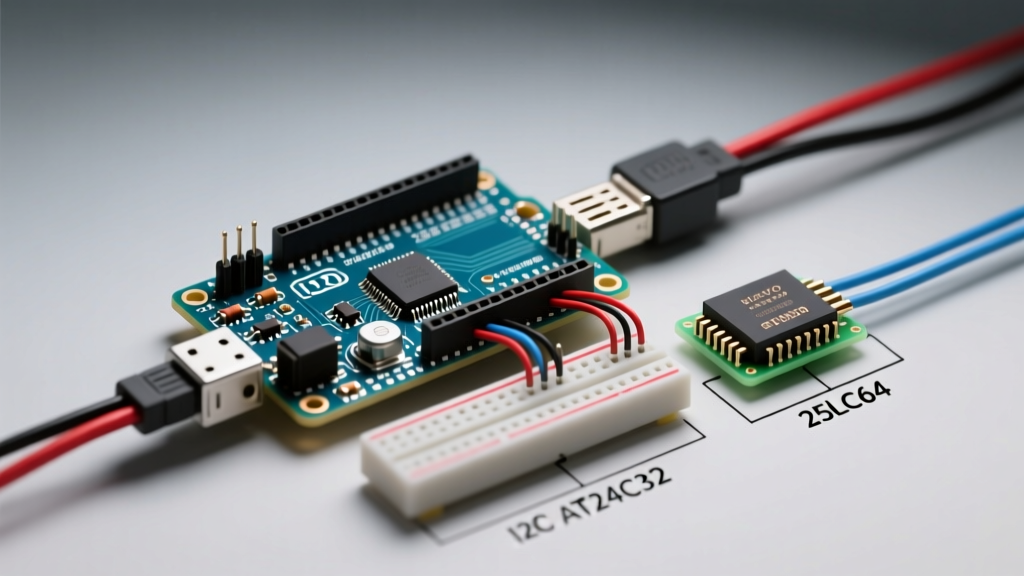
Consequently, pairing an Arduino with external EEPROM is no longer just an option for high-capacity needs; it is a strict requirement for cross-platform compatibility. This guide breaks down the hardware compatibility, wiring topologies, and hidden firmware traps when interfacing Arduino boards with I2C (AT24C series) and SPI (25LC series) external EEPROM chips.
Protocol Matrix: I2C vs. SPI EEPROM Compatibility
Choosing between I2C and SPI dictates your wiring complexity, bus speed, and pin consumption. Below is a technical comparison of the two most prevalent external EEPROM families used in the maker ecosystem.
| Feature | I2C EEPROM (AT24C256) | SPI EEPROM (25LC640A) |
|---|---|---|
| Capacity | 32 KB (256 Kbit) | 64 KB (512 Kbit) |
| Interface | 2-Wire (SDA, SCL) | 4-Wire (SI, SO, SCK, CS) |
| Max Clock Speed | 1 MHz (Standard/Fast+) | 10 MHz |
| Page Size | 64 Bytes | 32 Bytes |
| Address Pins | 3 (A0, A1, A2) | None (Uses Chip Select) |
| Avg. Pricing (2026) | ~$1.15 (DIP-8) | ~$1.85 (DIP-8) |
I2C Compatibility: Wiring the AT24C Series
The Microchip AT24C series (specifically the AT24C256 and AT24C512) remains the gold standard for I2C data logging due to its low pin count. However, successful integration requires strict adherence to bus capacitance limits and pull-up resistor tuning.
Address Pin Configuration and Bus Limits
The AT24C256 features three address pins (A0, A1, A2). The base I2C address is 0x50 (binary 1010000). By tying these pins to either GND (LOW) or VCC (HIGH), you can configure up to eight distinct chips on the same I2C bus, yielding a theoretical maximum of 256KB of addressable memory. According to the NXP I2C-bus specification, the total bus capacitance must not exceed 400 pF. If you are routing long wires to a remote sensor node, this capacitance limit will cause signal degradation and ACK failures, making SPI a superior choice for distributed systems.
Pull-Up Resistor Tuning
I2C is an open-drain protocol; it requires pull-up resistors on both SDA and SCL lines. Many pre-assembled EEPROM breakout boards include 10kΩ pull-ups. While 10kΩ might work at 100 kHz on a short breadboard, it will cause severe rise-time failures at 400 kHz (Fast Mode).
- 100 kHz (Standard Mode): Use 4.7kΩ resistors.
- 400 kHz (Fast Mode): Use 2.2kΩ to 3.3kΩ resistors.
- 1 MHz (Fast+ Mode): Use 1kΩ resistors, ensuring your Arduino core supports the higher clock divider.
The Page Boundary Wrap-Around Trap
The most common firmware failure when using an Arduino with EEPROM over I2C is the Page Boundary Wrap-Around. EEPROM chips do not write byte-by-byte; they write in 'pages' to minimize internal high-voltage generation and reduce wear.
Critical Edge Case: The AT24C256 has a 64-byte page size. If you initiate a sequential write of 20 bytes starting at memory address55, the chip will write up to address63(the end of the page). The remaining 11 bytes will not spill over to address64; instead, they will wrap around and overwrite addresses0through10of that exact same page, silently corrupting your data.
To prevent this, your Arduino sketch must calculate the remaining bytes in the current page before executing a write. Utilizing the Arduino Wire library, you must chunk your payload so that no single Wire.endTransmission() block crosses a 64-byte boundary. Alternatively, leverage the ExtEEPROM library, which handles page-boundary chunking natively in the background.
SPI Compatibility: High-Speed 25LC Series
When data throughput is critical—such as buffering high-frequency accelerometer data before SD card writes—SPI EEPROMs like the Microchip 25LC640A are mandatory. SPI bypasses the 400pF capacitance limits of I2C and operates at clock speeds up to 10 MHz.
SPI Opcode Management
Unlike I2C, SPI EEPROMs do not use a device address byte. Instead, every transaction begins with an 8-bit opcode. When programming your Arduino, you must manually shift these opcodes out via the SPI.transfer() function:
- WREN (0x06): Write Enable. Must be sent before every single write operation. The chip resets this latch after every write cycle completes.
- WRITE (0x02): Followed by a 16-bit address and the data payload.
- READ (0x03): Followed by a 16-bit address; the chip then clocks out data continuously until the Chip Select (CS) pin is pulled HIGH.
- RDSR (0x05): Read Status Register. Used to poll the WIP (Write In Progress) bit. You must poll this bit to ensure the 5ms write cycle has finished before sending the next WREN command.
Because SPI requires four shared pins (MOSI, MISO, SCK) plus a dedicated Chip Select (CS) pin per chip, it scales poorly if you need multiple memory banks. However, for single-chip high-speed logging, the 25LC series paired with an Arduino Due or Portenta H7 offers unmatched performance.
Voltage Level Translation: 5V vs 3.3V Logic
A frequent hardware incompatibility arises when pairing 5V Arduinos (like the Uno R3 or Mega) with modern low-voltage memory. Fortunately, most standard AT24C series chips (e.g., AT24C256C) feature a wide VCC operating range of 1.7V to 5.5V, meaning their I/O pins are 5V tolerant and can connect directly to an ATmega328P without logic shifters.
However, if you are utilizing high-density SPI NOR Flash or specialized FRAM chips that are strictly rated for 3.3V, feeding 5V logic from the Arduino will destroy the silicon. Do not rely on simple resistor voltage dividers for I2C or SPI; the parasitic capacitance of the resistors will round off the square waves, causing missed clock edges at high speeds.
The Expert Solution: Use a dedicated bidirectional logic level shifter based on N-channel MOSFETs (like the BSS138). SparkFun and Adafruit offer breakout boards utilizing this topology for under $4.00. For SPI buses running above 4 MHz, you must use an active driver IC like the Texas Instruments TXS0108E to maintain sharp rise and fall times, ensuring the EEPROM accurately registers the clock pulses.
Endurance and Data Retention Realities
When architecting your storage, consult the Microchip Serial EEPROM datasheets for endurance metrics. Both the AT24C and 25LC families are rated for 1,000,000 erase/write cycles and 100-year data retention at 25°C. If your Arduino is logging a sensor reading every 10 seconds, a single memory address will burn out in roughly 115 days. Always implement software-level wear leveling or circular buffering in your sketch to distribute writes evenly across the 32KB or 64KB address space, effectively multiplying the lifespan of the chip by thousands of times.