
Understanding the Backbone of Microcontroller Debugging
Whether you are blinking your first LED or engineering a multi-node IoT sensor array, understanding how to use serial communication in Arduino is the most critical skill in your firmware toolkit. Serial communication, specifically Universal Asynchronous Receiver-Transmitter (UART), allows your microcontroller to talk to your computer, external GPS modules, cellular modems, and secondary processors. In 2026, with the maker ecosystem heavily skewed toward 3.3V logic architectures like the ESP32-S3, Raspberry Pi RP2350, and Arduino Nano 33 IoT, mastering UART goes far beyond simply calling Serial.println().
This concept explainer dives deep into the physics of UART framing, hardware versus software serial constraints, voltage level translation, and advanced buffer management to ensure zero data loss in high-speed telemetry applications.
The Physics and Logic of UART Framing
UART is an asynchronous protocol, meaning it does not rely on a shared clock signal between the transmitter (TX) and receiver (RX). Instead, both devices must agree on a specific baud rate (bits per second) beforehand. According to SparkFun's Serial Communication Tutorial, a standard UART data frame consists of 10 bits:
- Start Bit (1 bit): Always low (0). Signals the receiving hardware that a byte is incoming.
- Data Bits (8 bits): The actual payload, sent least significant bit (LSB) first.
- Parity Bit (Optional): Used for basic error checking (Even/Odd). Rarely used in modern Arduino sketches.
- Stop Bit (1 or 2 bits): Always high (1). Gives the receiver time to process the byte and reset for the next frame.
At the standard debugging baud rate of 115200, a single 10-bit frame takes approximately 86.8 microseconds to transmit. This timing becomes critical when calculating interrupt latencies and buffer overflow thresholds in high-speed data logging scenarios.
Hardware Serial vs. SoftwareSerial: Architecture Constraints
When learning how to use serial communication in Arduino, you will encounter two primary methods: Hardware UART and SoftwareSerial. Hardware UART utilizes dedicated silicon on the microcontroller (like the ATmega328P or ESP32) to handle bit-shifting via interrupts. SoftwareSerial uses CPU timer interrupts to manually toggle GPIO pins (bit-banging) to emulate a UART port.
| Feature | Hardware UART (Serial1, Serial2) | SoftwareSerial (Bit-Banging) |
|---|---|---|
| CPU Overhead | Negligible (Handled by silicon FIFO) | Extremely High (Blocks main loop) |
| Max Reliable Baud | Up to 2,000,000+ (MCU dependent) | 57,600 (16MHz AVR) / 115,200 (ESP32) |
| Pin Flexibility | Fixed to specific TX/RX pin pairs | Any digital GPIO pin |
| Interrupt Safety | Safe during ISR execution | Fails if interrupts are disabled |
| Simultaneous Ports | Multiple (e.g., ESP32 has 3 UARTs) | Only one can listen at a time |
Reference: Arduino SoftwareSerial Documentation
Expert Tip for 2026 Architectures: If you are using an ESP32-S3 or RP2350, avoid SoftwareSerial entirely. These modern MCUs feature programmable I/O matrices or PIO (Programmable I/O) blocks that allow you to map hardware-level UART peripherals to almost any GPIO pin without CPU bit-banging penalties.
Advanced Data Parsing: Moving Beyond Serial.println()
Beginners often use blocking functions like Serial.readString(), which halts the main loop until a timeout occurs (default 1000ms). In real-time robotics or drone telemetry, a 1-second blocking delay is catastrophic. Instead, professional firmware relies on non-blocking character-by-character parsing using a custom ring buffer or the Serial.readStringUntil() method paired with a delimiter.
// Non-blocking Serial Parsing Example
String inputString = "";
bool stringComplete = false;

void setup() {
  Serial.begin(115200);
  inputString.reserve(64); // Pre-allocate memory to prevent heap fragmentation
}

void loop() {
  while (Serial.available()) {
    char inChar = (char)Serial.read();
    if (inChar == '\n') {
      stringComplete = true;
    } else {
      inputString += inChar;
    }
  }

  if (stringComplete) {
    processCommand(inputString);
    inputString = "";
    stringComplete = false;
  }

  // Main loop continues to run without blocking
  runMotorControl();
}
The Hidden Danger: 5V vs 3.3V Logic Level Translation
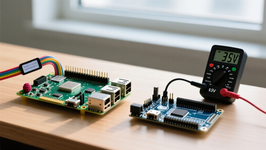
The most common hardware failure mode when wiring serial communication is voltage mismatch. The classic Arduino Uno (ATmega328P) operates at 5V logic. Modern peripherals, including the SIM7600 4G LTE module, ESP32, and most I2C/SPI sensors, operate at 3.3V logic.
Connecting a 5V Arduino TX pin directly to a 3.3V ESP32 RX pin will inject 5V into the ESP32's silicon, eventually degrading the gate oxide and permanently destroying the GPIO pin or the entire microcontroller. To solve this, you must use a logic level shifter.
Recommended Level Shifters for UART
- Texas Instruments TXB0108: An 8-channel bidirectional translator with auto-direction sensing. Ideal for high-speed UART up to 50 Mbps. Costs approximately $1.85 on Mouser. See the TI TXB0108 Datasheet for propagation delay specs.
- BSS138 MOSFET Breakouts: The SparkFun Logic Level Converter (BOB-12009, ~$2.95) uses BSS138 N-channel MOSFETs. While excellent for I2C, they struggle with UART baud rates above
115200due to gate capacitance rise-time delays. Stick to dedicated ICs like the TXB0108 or TXS0102 for serial lines exceeding 250k baud.
Real-World Troubleshooting & Edge Cases
Even seasoned engineers encounter serial anomalies. Here is a diagnostic matrix for the most frequent UART edge cases:
1. Garbled Output (Wingdings and Question Marks)
Cause: Baud rate mismatch between the transmitter and the Serial Monitor.
Fix: Ensure Serial.begin(115200) exactly matches your terminal software (PuTTY, TeraTerm, or Arduino IDE 2.x Serial Monitor). Note that internal RC oscillators on cheaper ATtiny85 clones can drift by up to 5%, causing framing errors at high baud rates. Drop to 9600 or 38400 if using uncalibrated internal clocks.
2. Missing Characters in Long Data Streams
Cause: Hardware RX Buffer Overflow. The ATmega328P has a hardcoded 64-byte RX buffer. If your main loop takes longer than ~5.5ms to execute (at 115200 baud), the buffer fills up, and incoming bytes are silently dropped.
Fix: Increase the buffer size by editing HardwareSerial.h in the Arduino core and changing #define SERIAL_RX_BUFFER_SIZE 64 to 256. Alternatively, implement DMA (Direct Memory Access) if using an ARM Cortex-M0+ board like the Arduino Zero.
3. ESP32 Boot Loops When Serial is Connected
Cause: GPIO Strapping Pin conflicts. On the original ESP32, GPIO 1 (TX0) and GPIO 3 (RX0) are tied to the boot sequence. If an external peripheral pulls GPIO 3 LOW during a reset, the ESP32 enters the serial bootloader and halts your sketch.
Fix: Never use the default UART0 pins for external peripherals on the ESP32. Remap your external serial devices to UART1 or UART2 using custom pins (e.g., Serial1.begin(115200, SERIAL_8N1, RX_PIN, TX_PIN)).
Frequently Asked Questions (FAQ)
Can I use multiple hardware serial ports on an Arduino Uno?
No. The ATmega328P only contains one hardware UART (UART0), which is shared with the USB-to-Serial ATmega16U2 chip for programming. If you need a second port on an Uno, you must use SoftwareSerial, but it is highly recommended to upgrade to an Arduino Mega 2560 (4 hardware UARTs) or an ESP32 (3 hardware UARTs) for multi-device serial routing.
What is the maximum cable length for UART serial communication?
UART is designed for point-to-point communication on a PCB or short cables. Because it uses unbalanced single-ended signaling (referenced to ground), it is highly susceptible to electromagnetic interference (EMI). Over standard jumper wires, keep UART traces under 50 cm. For long-distance serial communication (up to 1200 meters), you must convert the UART signal to RS-485 using a differential transceiver like the MAX485.
How do I clear the serial buffer in Arduino?
To flush incoming garbage data before reading a critical sensor response, use a simple while loop: while(Serial.available() > 0) { Serial.read(); }. Avoid using Serial.flush() for this purpose; in modern Arduino cores, flush() only blocks until the outgoing TX buffer is empty, it does not clear the RX buffer.
Conclusion
Mastering how to use serial communication in Arduino requires moving past basic print statements and understanding the underlying hardware constraints. By respecting voltage logic levels, utilizing hardware UART over software emulation, and managing your RX buffers effectively, you can build robust, crash-proof telemetry systems capable of handling the demands of modern 2026 IoT ecosystems.