
Beyond the Kit: Understanding Arduino Drone Architecture
When makers ask how to create a drone with Arduino, they are often looking for a simple wiring diagram. However, building a stable, multirotor aircraft from scratch using a general-purpose microcontroller is a profound exercise in embedded systems engineering. Unlike dedicated flight controllers running optimized firmware like Betaflight or ArduPilot on 32-bit ARM Cortex-M processors, an 8-bit Arduino requires you to manually manage sensor fusion, hardware timer interrupts, and Proportional-Integral-Derivative (PID) control loops.
This concept explainer bypasses basic plug-and-play tutorials. Instead, we deconstruct the core architecture of an Arduino-based quadcopter, examining the mathematical and electrical realities of turning an ATmega328P into a viable flight controller in 2026.
The Brains: Microcontroller Limitations and Loop Rates
The standard Arduino Nano or Uno utilizes the ATmega328P, clocked at 16 MHz. In a drone, the microcontroller must read sensors, calculate stabilization math, and output motor commands in a continuous loop. The speed of this loop (measured in Hertz) dictates how quickly the drone can react to wind gusts or pilot inputs.
Dedicated STM32F7-based flight controllers operate at 216 MHz, achieving control loop rates of 8 kHz (8,000 calculations per second). The ATmega328P, constrained by its slower clock and the overhead of I2C communication, typically maxes out at a stable 250 Hz to 400 Hz loop rate when reading an external IMU. While 250 Hz is sufficient for a stable, slow-flying cinematic or beginner quadcopter, it lacks the aggressive snap and responsiveness required for FPV freestyle flying. Understanding this hardware ceiling is critical when setting your performance expectations.
The Inner Ear: IMU Sensor Fusion and the MPU-6050
To know its orientation in 3D space, the Arduino relies on an Inertial Measurement Unit (IMU). The most common entry-level IMU is the InvenSense MPU-6050, which combines a 3-axis accelerometer and a 3-axis gyroscope. According to the official TDK InvenSense MPU-6050 documentation, the chip features an I2C interface and a Digital Motion Processor (DMP) that can offload some sensor fusion calculations.
The Complementary Filter
Gyroscopes measure the rate of rotation. By integrating this rate over time, you get an angle. However, gyroscopes suffer from drift due to thermal noise and integration errors. Accelerometers measure static acceleration (gravity) to determine absolute tilt, but they are incredibly noisy and highly sensitive to the high-frequency vibrations of brushless motors.
To solve this, you must implement a Complementary Filter in your Arduino sketch. This algorithm fuses the short-term accuracy of the gyroscope with the long-term stability of the accelerometer:
angle = 0.98 * (angle + gyro_rate * dt) + 0.02 * accelerometer_angle;
The 0.98 weighting trusts the gyro for immediate movements, while the 0.02 weighting gently pulls the calculated angle back to the accelerometer's absolute reference, eliminating gyro drift without introducing motor vibration noise.
Actuation: Escaping the 50Hz PWM Trap
Electronic Speed Controllers (ESCs) translate digital signals into 3-phase AC power for brushless motors. Beginners often use the default Arduino Servo.h library to send signals to ESCs. This is a critical mistake. Servo.h outputs a standard 50 Hz PWM signal, meaning a new motor command is only sent every 20 milliseconds. In a fast-flying drone, a 20ms latency between a PID correction and a motor response will result in violent oscillations and a crash.
To achieve a 400 Hz update rate (a command every 2.5ms), you must bypass Servo.h and manipulate the ATmega328P hardware timers directly. Using the TimerOne library, you can configure Timer1 to generate precise microsecond pulses (typically 1000µs to 2000µs) at a much higher frequency, drastically reducing control latency.
2026 Component Matrix: The Arduino Drone BOM
Building a reliable platform requires matching components that respect the Arduino's voltage and processing limits. Below is a targeted Bill of Materials (BOM) for a stable 5-inch quadcopter platform.
| Component | Specific Model / Specification | Estimated Cost (2026) | Architectural Role |
|---|---|---|---|
| Microcontroller | Arduino Nano (ATmega328P) Clone | $8.00 | Flight Controller / PID Math |
| IMU Sensor | GY-521 Module (MPU-6050) | $6.50 | 6-Axis Attitude Estimation |
| Power Regulator | Pololu 5V, 5A Step-Down BEC (D24V50F5) | $14.00 | Switches 16.8V LiPo to clean 5V |
| ESC | AM32 / BLHeli_32 45A 4-in-1 | $55.00 | Motor Commutation (PWM Input) |
| Motors (x4) | Emax ECO II 2207 1700KV | $76.00 | Thrust Generation (4S Optimized) |
| Frame | TBS Source One V5 (5-inch) | $45.00 | Carbon Fiber Chassis |
| Battery | CNHL 1500mAh 4S 100C LiPo | $38.00 | High-Discharge Power Source |
The Math: Tuning the PID Control Loop
The PID controller is the mathematical heart of your drone. It calculates the error (the difference between your desired angle via the RC receiver and your actual angle via the IMU) and outputs a corrective value to the motors.
- Proportional (P): Reacts to the present error. If the drone is tilted 10 degrees off-center, P applies immediate motor thrust to correct it. Too high, and the drone vibrates aggressively; too low, and it feels sluggish.
- Integral (I): Reacts to accumulated past error. If a steady wind pushes the drone, P alone won't fully correct it. I builds up over time to apply a constant counter-force, eliminating steady-state error.
- Derivative (D): Predicts future error by measuring the rate of change. It acts as a damper, preventing the P-term from overshooting the target angle. D is highly sensitive to IMU noise, which is why filtering is mandatory.
Manual Tuning Protocol
- Set I and D to zero. Gradually increase P until the drone oscillates rapidly on the bench, then reduce P by 30%.
- Introduce D to dampen the remaining P oscillations. Increase D until motor temperatures rise or high-frequency buzzing occurs, then back off slightly.
- Add I in small increments to ensure the drone holds its angle against wind resistance without drifting after aggressive stick inputs.
Power Distribution and the Voltage Regulator Trap
A massive point of failure for DIY Arduino drones is power delivery. A standard 4S LiPo battery has a nominal voltage of 14.8V, but a fully charged pack outputs 16.8V. The Arduino Nano features an onboard linear voltage regulator designed to step down unregulated voltage to 5V. However, linear regulators dissipate excess voltage as heat. Feeding 16.8V into the Nano's VIN pin while drawing just 100mA for the IMU and receiver will cause the onboard regulator to overheat, trigger thermal shutdown, and drop the drone out of the sky.
The Solution: Never power an Arduino flight controller directly from a 4S LiPo via the VIN pin. Always use an external, high-efficiency switching BEC (Battery Eliminator Circuit), such as the Pololu 5V 5A Step-Down Regulator. This safely steps the 16.8V down to a clean, ripple-free 5V, which is then fed directly into the Arduino's 5V pin, bypassing the inefficient onboard linear regulator entirely.
Safety Warning: Never tune PID values or test motor directions with propellers attached. An Arduino sketch crash, an I2C bus lockup, or a loose jumper wire will result in uncontrolled motor spin-ups. Always use a bench power supply with a strict current limit (e.g., 2 Amps) during initial code deployment and sensor calibration.
Real-World Failure Modes: EMI and I2C Lockups
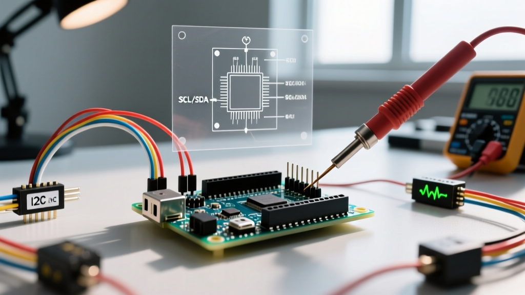
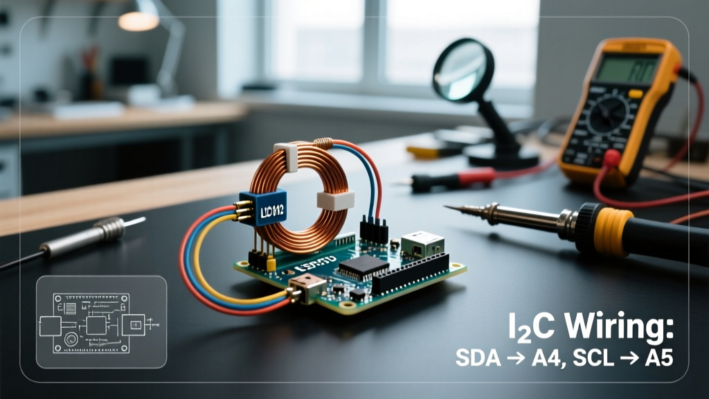
Brushless motors and high-frequency ESCs generate massive Electromagnetic Interference (EMI). The MPU-6050 communicates with the Arduino via the I2C protocol, which is notoriously susceptible to noise. If an EMI spike corrupts the I2C data line (SDA), the Arduino's Wire library will hang indefinitely waiting for a clock signal, resulting in a frozen flight controller and an immediate crash.
To engineer around this edge case, you must implement three hardware safeguards:
- Pull-Up Resistors: The GY-521 breakout board has weak internal pull-ups. Solder external 4.7kΩ pull-up resistors between the SDA/SCL lines and the 5V rail to stiffen the bus against noise.
- Twisted Pair Wiring: Twist your SDA and SCL wires together. This ensures that any EMI spike induces a common-mode voltage that the I2C receiver will reject.
- Software Watchdog: Enable the ATmega328P hardware Watchdog Timer (WDT) in your code. If the I2C bus locks up and the main loop stalls for more than 250 milliseconds, the WDT will automatically hard-reset the microcontroller, potentially saving the aircraft if it occurs at a high enough altitude.
Conclusion: The Educational Value of the Arduino Drone
While modern off-the-shelf flight controllers offer superior performance, learning how to create a drone with Arduino remains one of the most rewarding projects in the maker community. By wrestling with hardware timers, writing your own complementary filters, and debugging I2C noise, you transition from a consumer of technology to a true embedded systems engineer. For further reading on open-source flight dynamics, the ArduPilot open-source project provides an incredible repository of advanced sensor fusion and navigation algorithms that originated from these exact foundational concepts.