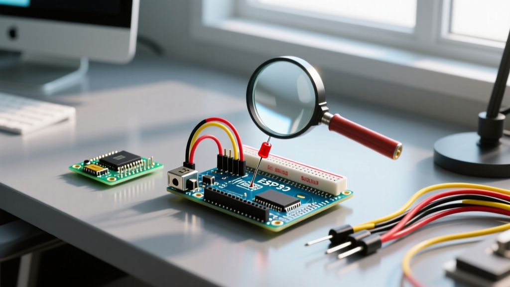

The Reality of Arduino LED Wire Troubleshooting
Blinking an LED is universally recognized as the 'Hello World' of microcontroller programming. However, when your Arduino LED wire setup refuses to illuminate, the simplicity of the project quickly devolves into a frustrating hardware debugging session. Whether you are working with standard 5mm through-hole indicators, high-power illumination modules, or addressable WS2812B strips, a failure to light up almost always traces back to physical layer discontinuities, component mismatches, or logic-level errors.
In this comprehensive 2026 troubleshooting guide, we bypass the generic 'check your code' advice and dive deep into the electrical and physical failure modes of Arduino LED circuits. We will cover wire gauge limitations, breadboard contact fatigue, forward voltage miscalculations, and addressable data-line degradation.
Phase 1: Physical Layer and Wire Integrity
Before touching the IDE, you must verify the physical medium carrying your current and logic signals. Jumper wires and breadboards are the most common points of failure in prototype circuits.
Breadboard Contact Fatigue and High Resistance
Standard solderless breadboards use leaf-spring contacts designed for 20 AWG to 26 AWG solid-core wire. If you frequently insert and remove 28 AWG stranded jumper wires, the contacts can stretch, leading to high contact resistance. A contact resistance exceeding 5 ohms will cause a noticeable voltage drop, starving low-current LEDs of the necessary forward voltage.
Pro Tip: If you suspect breadboard fatigue, move your LED and resistor to a completely different power rail. Breadboard power rails are notorious for having hidden splits in the middle (often indicated by a red/blue line break) that makers accidentally bridge or fail to bridge.
Jumper Wire Internal Fractures
Cheap Dupont-style jumper wires often fail internally right behind the crimped plastic housing. The wire looks intact, but the copper strands have snapped due to repeated bending.
- Set your multimeter to continuity mode (the diode/sound icon).
- Insert the probes into the female/male ends of the suspect Arduino LED wire.
- Wiggle the wire near the plastic housing. If the multimeter beeps intermittently, the crimp has failed and the wire must be discarded.
Phase 2: Component Verification and Sizing
If the wires have continuity, the next culprit is usually a mismatch between the microcontroller's output voltage, the LED's forward voltage (Vf), and the current-limiting resistor.
Forward Voltage and Resistor Matrix
Connecting an LED directly to an Arduino digital pin without a resistor will either destroy the LED, fry the ATmega328P's internal IO pin (max 40mA per pin, 200mA total package limit), or trigger the board's thermal shutdown. Use the table below to select the correct resistor for a standard 5V Arduino (like the Uno R4 or Nano).
| LED Color | Typical Forward Voltage (Vf) | Target Current (mA) | Required Resistor (at 5V) |
|---|---|---|---|
| Red (Standard 5mm) | 2.0V - 2.2V | 20mA | 150Ω or 220Ω |
| Yellow / Green | 2.1V - 2.4V | 20mA | 150Ω or 220Ω |
| Blue / White / UV | 3.0V - 3.4V | 20mA | 100Ω or 150Ω |
| Infrared (IR) | 1.2V - 1.5V | 50mA (Check datasheet) | 68Ω or 75Ω |
Note: Always round up to the nearest standard E12/E24 resistor value to ensure you do not exceed the LED's maximum continuous forward current.
Polarity and the Flat Edge Rule
It sounds elementary, but reversed polarity accounts for nearly 30% of beginner LED failures. The short leg (cathode) must connect to ground (GND), and the long leg (anode) connects to the digital pin via the resistor. If the legs have been clipped, look for the flat notch on the plastic rim of the LED housing—that flat side indicates the cathode.
Phase 3: Addressable LED Wire Issues (WS2812B / NeoPixel)
Addressable LEDs introduce a data wire into the mix, complicating the troubleshooting process. If your standard power and ground are correct but the strip remains dead or flickers erratically, the issue lies in data signal integrity.
The 50cm Data Wire Limit
The data signal for WS2812B LEDs operates at 800 KHz. High-frequency digital signals are highly susceptible to capacitive loading and electromagnetic interference (EMI). If your Arduino LED wire carrying the data signal exceeds 50 centimeters (approx. 20 inches), the signal will degrade, resulting in the first LED lighting up but subsequent LEDs failing or displaying random colors.
- Fix 1: Keep the data wire from the Arduino to the first LED under 30cm.
- Fix 2: Add a 300Ω to 500Ω resistor directly at the DIN pin of the first LED to prevent ringing and reflections on the data line.
- Fix 3: For long runs, use a differential signaling pair (like RS-485) or inject the data signal closer to the strip using a secondary level shifter.
Logic Level Shifting (3.3V vs 5V)
Modern microcontrollers, including the ESP32 and Arduino Nano 33 IoT, operate at 3.3V logic. However, WS2812B LEDs require a data-high signal of at least 0.7 x VDD (which is 3.5V for a 5V strip). Feeding a 3.3V data signal into a 5V LED strip will cause erratic behavior. As detailed in the Adafruit NeoPixel Überguide, you must use a 74AHCT125 level shifter to boost the 3.3V data signal to a clean 5V square wave.
Phase 4: Voltage Drop in Long Power Runs
When wiring high-density LED strips (e.g., 60 LEDs/meter), a standard 28 AWG breadboard jumper wire cannot carry the required current. A fully lit white strip of 60 WS2812B LEDs draws approximately 3.6 Amps. Pushing 3.6A through thin jumper wires will result in massive voltage drop, causing the LEDs at the end of the strip to turn brown or red, or the Arduino to brownout and reset.
According to standard wire resistance charts, 24 AWG copper wire has a resistance of roughly 25.67 ohms per 1,000 feet. For a 3A load over a 2-foot round trip, you will lose nearly 0.15V just in the wire. For high-current runs, abandon breadboard jumper wires entirely. Use silicone-jacketed 18 AWG or 16 AWG wire, and solder the connections directly to the LED strip's copper pads. Furthermore, always place a 470µF to 1000µF electrolytic capacitor across the 5V and GND terminals at the start of the strip to buffer transient current spikes.
Phase 5: Software-to-Hardware Bridge
If the hardware passes all multimeter tests, the fault lies in the firmware configuration. Referencing the official Arduino Blink documentation, ensure your code aligns with the physical board.
Common Code-Level Pitfalls
- Missing pinMode(): While modern Arduino cores default pins to INPUT, failing to explicitly declare
pinMode(LED_PIN, OUTPUT);in thesetup()function can result in the pin acting as a high-impedance input, providing barely enough leakage current to faintly glow the LED. - PWM vs. Digital Pins: If you are using
analogWrite()to dim the LED, ensure your Arduino LED wire is connected to a PWM-capable pin (marked with a ~ on the Uno/Nano). Pins like D2, D4, D7, and D8 on the ATmega328P do not support hardware PWM; the LED will simply turn fully on or off. - Pin Conflicts: Avoid using D0 (RX) and D1 (TX) for LED outputs. These pins are tied to the onboard USB-to-Serial converter. An LED connected here will interfere with code uploading and cause the onboard TX/RX LEDs to behave erratically.
Summary Diagnostic Checklist
When your Arduino LED wire setup fails, run through this rapid diagnostic sequence:
- Visual Check: Verify LED polarity (flat edge to GND) and resistor presence.
- Continuity Test: Use a multimeter to check the jumper wires for internal crimp fractures.
- Voltage Check: Measure the voltage directly at the LED anode while the pin is driven HIGH. It should read close to 5V (minus the resistor drop).
- Addressable Check: If using NeoPixels, verify the 300Ω data resistor, the 470µF bulk capacitor, and ensure data wire length is under 50cm.
- Code Check: Confirm
pinModeis set to OUTPUT and the correct pin number is targeted.
By systematically isolating the physical, electrical, and logical layers of your circuit, you can resolve almost any LED wiring failure in minutes, getting you back to building more complex embedded systems.