
The Industrial Standard Meets the Maker Bench
In the world of industrial automation, the 4-20mA current loop is the undisputed king of analog signal transmission. Whether you are monitoring the pressure in a hydraulic press, measuring the flow rate of a chemical dosing pump, or tracking the level of a municipal water tank, industrial sensors almost universally output a 4-20mA signal. But what happens when you need to bring this robust, factory-floor data into a low-voltage, 5V microcontroller environment? Building a reliable Arduino 4 20mA loop interface requires more than just connecting a few wires; it demands a solid understanding of signal conditioning, impedance matching, and galvanic isolation.
This comprehensive guide breaks down the physics, mathematics, and hardware topologies required to safely and accurately interface an Arduino (or any similar MCU like the ESP32) with industrial 4-20mA transmitters in 2026.
Why Current Instead of Voltage?
Before diving into the circuit design, it is crucial to understand why the industry relies on current rather than voltage. If you transmit a 0-5V signal over 100 meters of copper wire, the resistance of the wire will cause a voltage drop. The receiving end might only see 4.2V, leading to massive measurement errors. Furthermore, voltage signals are highly susceptible to Electromagnetic Interference (EMI) from heavy machinery, VFDs (Variable Frequency Drives), and radio frequencies.
A current loop, however, is immune to voltage drops over distance. According to Kirchhoff's Current Law, the current remains constant throughout a series circuit. As long as the power supply provides enough compliance voltage to overcome the total resistance of the loop, the current at the receiver will perfectly match the current generated by the sensor. Additionally, the "live zero" at 4mA allows the system to distinguish between a genuine zero reading (4mA) and a broken wire or dead sensor (0mA). For advanced diagnostics, the industry uses the NAMUR NE43 standard, which defines currents below 3.8mA or above 20.5mA as specific hardware fault indicators.
The Core Mathematics: Converting Current to Voltage
Microcontrollers cannot read current directly; their Analog-to-Digital Converters (ADCs) measure voltage. Therefore, we must convert the 4-20mA current into a proportional voltage using a precision shunt resistor, applying Ohm's Law (V = I × R).
Choosing the Right Shunt Resistor
The industry-standard shunt resistor value is 250 ohms. Let us look at the math:
- At 4mA (0.004A): V = 0.004 × 250 = 1.0V
- At 20mA (0.020A): V = 0.020 × 250 = 5.0V
This perfectly maps the sensor's output to the 0-5V ADC range of a classic Arduino Uno. However, as of 2026, most modern makers and engineers prefer the Arduino Uno R4 Minima (retailing around $27), which features a 14-bit ADC, or they use an external 16-bit ADC like the ADS1115 for higher resolution. If you use a 250-ohm resistor, it must be a 0.1% tolerance precision resistor (such as those from Vishay or Bourns, costing about $1.50). A standard 5% carbon film resistor will introduce unacceptable baseline errors.
Three Hardware Topologies for Interfacing
Depending on your environment and budget, there are three primary ways to wire an Arduino 4-20mA loop interface. According to design guidelines published by Analog Devices, selecting the right topology is critical for avoiding ground loops and common-mode noise.
1. The Simple Shunt (Non-Isolated)
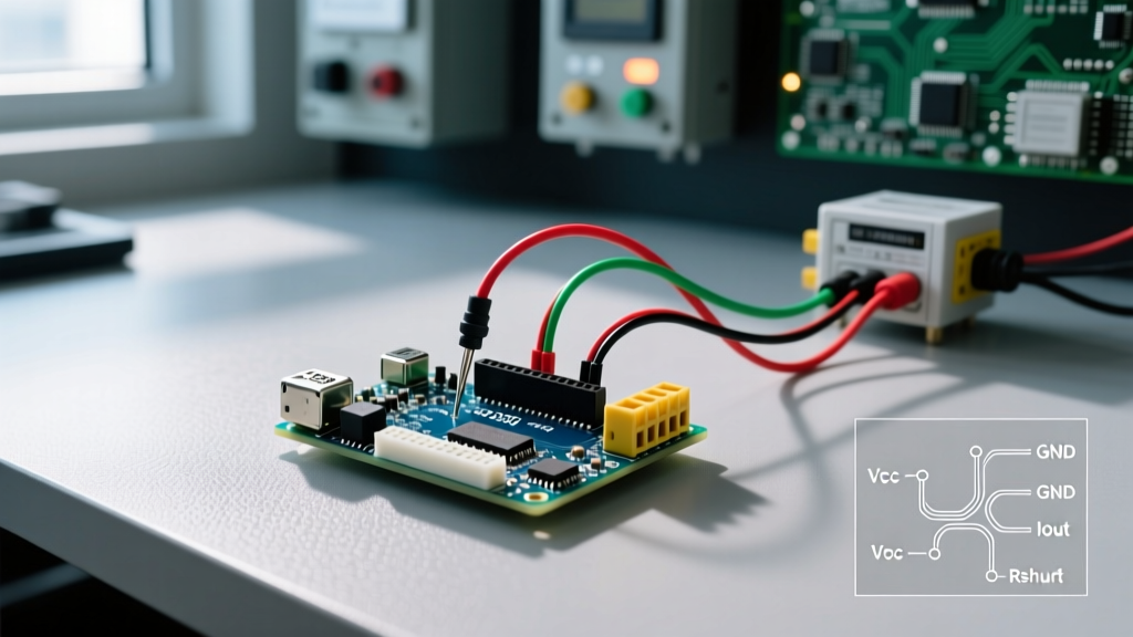
This method places the 250-ohm resistor directly between the sensor's ground and the Arduino's ground. The voltage is read at the junction.
- Pros: Extremely cheap (under $2 in components); easy to wire.
- Cons: Zero galvanic isolation. If the sensor is grounded to a different potential than the Arduino (common in industrial panels), a ground loop will form, potentially frying the microcontroller's ADC pin.
2. Instrumentation Amplifier (In-Amp)
Using a chip like the Texas Instruments INA333 or INA828, you can measure the voltage drop across a smaller shunt resistor (e.g., 100 ohms, yielding 0.4V to 2.0V) and amplify it while rejecting common-mode noise.
- Pros: Excellent Common-Mode Rejection Ratio (CMRR); protects the MCU from minor voltage spikes.
- Cons: Requires a dual or split power supply for some In-Amps; still shares a common ground reference, meaning severe ground faults can still cause damage.
3. Galvanic Isolation (Industrial Grade)
For harsh environments, you use an isolation amplifier like the TI ISO124 or the AMC1301. These chips use internal capacitive or magnetic barriers to transmit the analog signal without any physical electrical connection between the sensor loop and the Arduino.
- Pros: 100% protection against ground loops and high-voltage transients; mandatory for medical or heavy industrial applications.
- Cons: Higher cost (isolation ICs cost $10-$18); requires isolated DC-DC power supplies on both sides of the barrier.
Topology Comparison Matrix
| Topology | Estimated Cost (2026) | Galvanic Isolation | Noise Immunity | Best Use Case |
|---|---|---|---|---|
| Simple 250Ω Shunt | $1.50 | No | Low | Bench testing, isolated battery-powered sensors |
| Instrumentation Amp | $6.00 | No | High | Clean factory floors, shared ground systems |
| Isolation Amplifier | $22.00+ | Yes | Extreme | Heavy machinery, VFD proximity, outdoor tanks |
Step-by-Step: Building a Precision Interface with the ADS1115
While the Arduino Uno R3's 10-bit internal ADC gives you roughly 0.02mA of resolution (which is adequate for basic water tank monitoring), precision applications require more. By pairing a 250-ohm shunt with an ADS1115 16-bit external ADC (available on breakout boards from Adafruit or SparkFun for about $11), you achieve a theoretical resolution of 0.0005mA. The Adafruit ADS1115 Guide provides excellent baseline libraries for I2C communication.
- Power the Sensor: Connect a 24V DC industrial power supply to the transmitter's positive terminal. Ensure the power supply can source at least 30mA to account for startup inrush.
- Wire the Shunt: Connect the transmitter's negative (signal) wire to one leg of the 250-ohm 0.1% precision resistor. Connect the other leg of the resistor to the system Ground.
- Connect the ADC: Wire the ADS1115 breakout to the Arduino via I2C (SDA to A4, SCL to A5 on classic Unos, or the dedicated I2C pins on the Uno R4).
- Route the Analog Signal: Connect the junction of the transmitter wire and the shunt resistor to the A0 pin on the ADS1115. Connect the system Ground to the GND pin on the ADS1115.
- Configure the PGA: In your Arduino sketch, set the ADS1115's Programmable Gain Amplifier (PGA) to ±6.144V. This ensures the 5V maximum drop across the shunt is well within the safe measurement range, preventing clipping.
Pro-Tip for Software Filtering: Industrial environments are electrically noisy. Even with a hardware RC low-pass filter (e.g., a 1kΩ series resistor and a 100nF capacitor to ground), you should implement a software moving-average filter or an exponential smoothing algorithm in your Arduino sketch to eliminate transient ADC jitter.
Edge Cases and Troubleshooting
When deploying an Arduino 4 20mA loop interface in the real world, you will inevitably encounter edge cases that do not appear in bench simulations.
The Compliance Voltage Trap
A common failure mode occurs when the loop power supply does not provide enough voltage. If your sensor requires 12V to operate internally, and your 250-ohm shunt drops 5V at full scale, the total loop voltage requirement is 17V. If you attempt to power this loop with a standard 12V wall adapter, the signal will clip and flatten out around 12mA because the sensor has run out of "headroom" (compliance voltage). Always use a 24V DC power supply for standard industrial loops to ensure adequate overhead for wire resistance and internal sensor drops.
Ground Loop Destruction
If your Arduino is powered via a USB connection to a PC, and the PC is grounded to the building's earth, while the 24V industrial power supply is also earth-grounded at a different physical location, a potential difference will exist between the two grounds. Current will flow through the Arduino's ground traces, bypassing the shunt resistor and instantly destroying the microcontroller. If you are unsure about the grounding topology of your deployment site, you must use galvanic isolation or power the Arduino via an isolated DC-DC converter.
Handling the "Live Zero" in Code
Remember that 4mA represents 0% of your physical measurement, not 0mA. When mapping your ADC readings in C++, do not use the standard map() function with a 0 lower bound. Instead, map the 1V-5V range (or the equivalent raw ADC values) to your 0-100% engineering units. Any reading below 3.8mA should trigger a software fault flag indicating a broken wire or sensor failure.
Conclusion
Interfacing an Arduino with a 4-20mA loop bridges the gap between hobbyist microcontrollers and professional industrial instrumentation. By understanding the underlying physics, selecting the correct precision shunt resistor, and choosing the appropriate signal conditioning topology—whether a simple shunt, an instrumentation amplifier, or a fully isolated barrier—you can build data-logging and control systems that are both highly accurate and robust enough to survive the harsh realities of the factory floor.