
Why Deploy an Arduino as a PLC?
Traditionally, Programmable Logic Controllers (PLCs) from legacy brands like Siemens, Allen-Bradley, or Omron require hefty capital expenditures, often starting at $500 to $2,000 for base units, plus expensive proprietary software licenses. For small-to-medium manufacturing cells, IoT edge nodes, or advanced educational labs, using an Arduino as a PLC bridges the gap between low-cost microcontroller prototyping and rugged industrial reliability.
By leveraging IEC 61131-3 compliant programming environments and industrial-grade Arduino hardware, makers and engineers can deploy ladder logic, function block diagrams, and structured text on a platform that natively understands 24V industrial signals. In this guide, we will walk through the exact hardware selection, wiring protocols, and software configuration required to transform an Arduino into a fully functional PLC.
Hardware Selection: Prototyping vs. True Industrial
Not all Arduinos are created equal when it comes to factory floors. Standard 5V logic boards will be destroyed by 24V industrial sensor transients and VFD (Variable Frequency Drive) EMI. Below is a comparison of viable hardware paths for configuring an Arduino as a PLC in 2026.
| Hardware Platform | Classification | Approx. Cost | I/O Voltage | Best Use Case |
|---|---|---|---|---|
| Arduino Mega 2560 + Relay Shield | Prototyping | $60 | 5V Logic / 24V Relays | Student labs, low-stakes dry runs, conveyor simulations |
| Arduino Opta (Lite/WiFi) | Industrial | $145 - $195 | 24V DC Native (Optoisolated) | Small manufacturing, IoT edge nodes, building automation |
| CONTROLLINO MAXI | Industrial | $280+ | 12V/24V DC Native | Harsh environments, marine automation, heavy machinery |
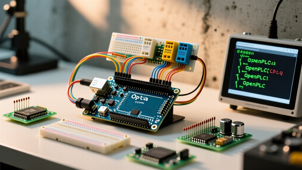
For this tutorial, we will focus on the Arduino Opta, as it represents the official, most accessible bridge between the Arduino ecosystem and true DIN-rail industrial automation. You can review the foundational hardware architecture in the Arduino Opta Getting Started Guide.
Step 1: Installing OpenPLC and the Runtime
To program an Arduino using standard industrial languages (Ladder Diagram, Structured Text, Function Block), we use OpenPLC, an open-source IEC 61131-3 compliant software suite.
- Download the Editor: Install the OpenPLC Editor on your Windows, macOS, or Linux machine.
- Flash the Runtime: Connect the Arduino Opta via USB-C. In the OpenPLC Editor, navigate to File > Upload Firmware to PLC. Select the correct board and COM port. This flashes the OpenPLC runtime onto the Opta, replacing the standard Arduino bootloader.
- Start the PLC: Once flashed, the Opta will boot into the OpenPLC runtime. The status LED will indicate it is waiting for a program via USB or Ethernet.
Critical Warning: Flashing the OpenPLC firmware overwrites the Arduino bootloader. If you ever need to revert to standard C++ Arduino IDE programming, you must use an external ST-Link V2 programmer or an ISP to burn the bootloader back onto the STM32H747XI chip inside the Opta.
Step 2: Wiring 24V Industrial Sensors to the Arduino Opta
Industrial automation relies on 24V DC logic. The Arduino Opta features 8 optoisolated digital inputs and 4 relay/SSD outputs. Let us wire a standard 3-wire PNP inductive proximity sensor (e.g., the widely used LJ12A3-4-Z/BX) to detect metallic parts on a conveyor.
PNP Sensor Wiring (Sourcing Input)
- Brown Wire: Connect to the 24V DC terminal on your DIN-rail power supply.
- Blue Wire: Connect to the 0V (GND) terminal on the power supply.
- Black Wire (Signal): Connect to Input I0 on the Arduino Opta.
When the sensor detects metal, it outputs 24V on the black wire. The Opta's internal optocoupler sinks this current, safely registering a logical HIGH without exposing the internal 3.3V STM32 microcontroller to the 24V line.
Protecting Outputs from Inductive Kickback
If you are switching inductive loads like 24V solenoid valves or DC motor contactors using the Opta's outputs, you must install a flyback diode (such as a 1N4007) in reverse bias across the load's coil. When the output transistor opens, the collapsing magnetic field generates a high-voltage spike (back-EMF) that can instantly destroy the output channel. The 1N4007 clamps this spike safely back into the coil.
Step 3: Writing Your First Ladder Logic Diagram (LD)
Industrial programmers rarely use C++ for PLCs; they use Ladder Logic. We will create a standard 'Start/Stop Seal-In' circuit for a conveyor motor.
- Open the OpenPLC Editor and create a new project.
- Define your I/O variables in the Variables tab:
%IX0.0(BOOL) - Start Button (Normally Open)%IX0.1(BOOL) - Stop Button (Normally Closed)%QX0.0(BOOL) - Motor Contactor Output
- Create a new Program Organization Unit (POU) and select LD (Ladder Diagram).
- Draw a rung with the Start button in parallel with the Motor Contactor output (the seal-in latch), placed in series with the Stop button, terminating at the Motor Contactor coil.
This structure adheres to the IEC 61131-3 Standard for programmable controllers, ensuring your logic is portable to other industrial platforms if you ever scale up to a Siemens S7-1200.
Step 4: Flashing and Modbus TCP Integration
Once your logic is compiled in the OpenPLC Editor, connect to the Opta via its USB-C virtual COM port or its Ethernet IP address (default is usually 192.168.1.100). Click Transfer PLC Program.
For enterprise integration, the Arduino Opta WiFi supports Modbus TCP out of the box when running the OpenPLC runtime. This allows you to connect the Opta to a SCADA system (like Ignition or Node-RED) over the local network. Simply enable the Modbus TCP server in the OpenPLC web dashboard, and map the %IX and %QX registers to your SCADA HMI tags for real-time monitoring.
Critical Failure Modes and Edge Cases
Deploying an Arduino as a PLC introduces specific edge cases that do not exist in pure software development. Be aware of these industrial failure modes:
- Ground Loops: Never power the Arduino Opta via USB-C while it is simultaneously connected to a 24V industrial PSU and grounded machinery. Differences in ground potential can push lethal current through the USB shield. Always use an isolated DC-DC converter (like the B0505S) if external USB communication is required during operation.
- VFD Electromagnetic Interference (EMI): Variable Frequency Drives generate massive electrical noise. If your sensor cables run parallel to VFD power cables, the Opta may register false triggers. Always use shielded twisted-pair (STP) cables for sensor wiring, and terminate the shield to the DIN-rail ground at one end only.
- Contact Bounce: Mechanical limit switches exhibit contact bounce. While the OpenPLC runtime has built-in filtering, highly vibrating environments may require you to add a software debounce timer (TON block) set to 20ms-50ms in your Ladder Logic.
Frequently Asked Questions
Can I use a standard Arduino Uno as a PLC?
Technically yes, using relay shields and OpenPLC, but it is strictly for educational prototyping. The Uno lacks optoisolation, native 24V I/O, and a watchdog timer, making it unsafe and unreliable for actual industrial machinery control.
Does OpenPLC support Structured Text (ST)?
Yes. OpenPLC fully supports all five IEC 61131-3 languages: Ladder Diagram (LD), Function Block Diagram (FBD), Structured Text (ST), Instruction List (IL), and Sequential Function Chart (SFC). You can mix and match these languages within different POUs in the same project.
How do I handle analog 4-20mA sensors with the Arduino Opta?
The standard Arduino Opta does not have native analog inputs. For 4-20mA pressure or temperature transmitters, you must either use an external I2C/SPI analog-to-digital converter module rated for industrial isolation, or upgrade to a specialized PLC shield from manufacturers like Industrial Shields.