
Introduction: Bridging the Microcontroller and the SBC
Combining an Arduino and a Raspberry Pi is a staple architecture in advanced maker projects, robotics, and industrial IoT prototypes. The Raspberry Pi handles high-level tasks like computer vision, database logging, and cloud API routing, while the Arduino manages deterministic, real-time hardware I/O, PWM motor control, and analog sensor reading. The most reliable, low-latency way to connect these two boards is via UART (Universal Asynchronous Receiver-Transmitter) serial communication.
However, bridging a 5V microcontroller and a 3.3V single-board computer introduces hardware risks and Linux configuration hurdles. This quick-reference FAQ provides exact wiring schematics, voltage math, OS configuration steps, and troubleshooting matrices to get your serial link running flawlessly.
Quick Reference: UART Pinout and Wiring Matrix
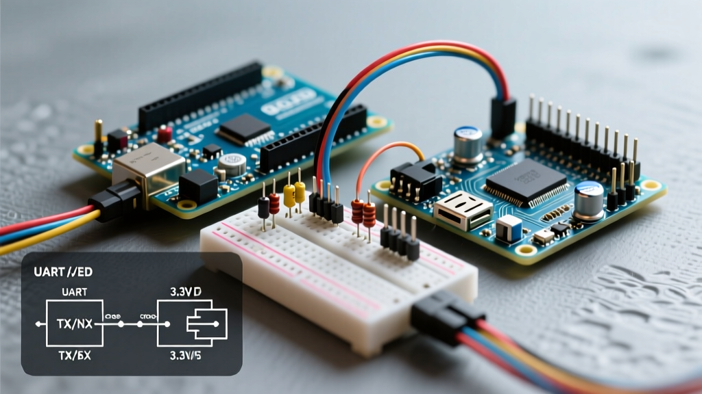
Before writing any code, you must establish the physical serial link. Always remember to cross the TX (Transmit) and RX (Receive) lines, and tie the grounds together.
| Raspberry Pi (3.3V Logic) | Signal Direction | Arduino Uno/Nano (5V Logic) | Notes & Warnings |
|---|---|---|---|
| GPIO 14 (Pin 8 / TXD) | Pi TX → Arduino RX | D0 (RX) | Direct connection is generally safe (3.3V is read as HIGH by 5V logic). |
| GPIO 15 (Pin 10 / RXD) | Pi RX ← Arduino TX | D1 (TX) | DANGER: Requires a logic level shifter or voltage divider. 5V will damage the Pi. |
| Ground (Pin 6) | Common Ground | GND | Mandatory to prevent floating grounds and signal noise. |
Hardware FAQs: Voltage Levels and Signal Integrity
Can I connect a 5V Arduino directly to a 3.3V Raspberry Pi?
No. While the Raspberry Pi's 3.3V TX output will safely register as a logical HIGH on the Arduino's 5V RX pin, the Arduino's 5V TX output will overvoltage and potentially destroy the Raspberry Pi's 3.3V RX GPIO pin. You must step down the 5V signal to 3.3V.
How do I build a safe voltage divider for the RX line?
If you do not have a dedicated logic level converter, you can build a voltage divider using two resistors. To drop 5V down to a safe ~3.0V (which the Pi reliably reads as HIGH), use a 2.2kΩ resistor (R1) and a 3.3kΩ resistor (R2).
The Math: Vout = Vin × (R2 / (R1 + R2))
Vout = 5V × (3300 / (2200 + 3300)) = 5V × 0.6 = 3.0V
Wiring: Connect Arduino TX to R1. Connect the other end of R1 to R2 and the Pi's RX (GPIO 15). Connect the other end of R2 to Ground.
What is the best commercial alternative to a resistor divider?
For high-speed baud rates (above 115200) or bidirectional buses like I2C, resistor dividers suffer from parasitic capacitance, rounding off the square waves. Use a bi-directional logic level converter based on the BSS138 MOSFET, such as the SparkFun Logic Level Converter (BOB-12009, ~$3.95) or generic Adafruit equivalents. These provide clean, fast edge transitions without signal degradation.
Software & OS Configuration FAQs
Why is my serial data garbage or completely missing on the Pi?
By default, Raspberry Pi OS routes the Linux boot console and login shell to the primary hardware UART (/dev/ttyAMA0). This spams boot logs to your Arduino and intercepts your data. You must disable the serial console while keeping the hardware port enabled.
Step-by-Step Fix:
- Open the terminal on your Pi and run:
sudo raspi-config - Navigate to Interface Options > Serial Port.
- When asked "Would you like a login shell to be accessible over serial?", select No.
- When asked "Would you like the serial port hardware to be enabled?", select Yes.
- Reboot the Pi.
For deeper details on UART mapping, consult the official Raspberry Pi UART configuration guide.
What is the Bluetooth UART Mux issue on Pi 3, 4, and 5?
On Raspberry Pi models with onboard Bluetooth, the high-performance PL011 UART (/dev/ttyAMA0) is routed to the Bluetooth chip, while the lower-performance "mini-UART" (/dev/ttyS0) is routed to the GPIO header. The mini-UART lacks a stable clock and will drop bytes at high baud rates.
The Fix: If your project does not require Pi Bluetooth, force the PL011 UART back to the GPIO pins by editing your boot config. Open /boot/firmware/config.txt (or /boot/config.txt on older OS versions) and add this line at the bottom:
dtoverlay=disable-btReboot, and always reference the stable symlink /dev/serial0 in your Python code, which automatically maps to the correct primary UART.
Code Implementation Quick-Start
Arduino C++ Sketch (Sender)
This sketch reads an analog sensor and sends a formatted CSV string every 500ms. Always use the Arduino Serial Reference for buffer management best practices.
void setup() {
  // 9600 baud is safest for long wires and software serial fallbacks
  Serial.begin(9600);
}

void loop() {
  int sensorVal = analogRead(A0);
  float voltage = sensorVal * (5.0 / 1023.0);

  // Send structured data
  Serial.print("SENSOR,");
  Serial.println(voltage, 2);

  delay(500);
}
Raspberry Pi Python Script (Receiver)
Use the pyserial library. Install it via pip3 install pyserial. Refer to the PySerial Short Introduction for advanced timeout configurations.
import serial
import time

# Always use the /dev/serial0 symlink for hardware independence
ser = serial.Serial(
    port='/dev/serial0',
    baudrate=9600,
    parity=serial.PARITY_NONE,
    stopbits=serial.STOPBITS_ONE,
    bytesize=serial.EIGHTBITS,
    timeout=1
)

try:
    while True:
        if ser.in_waiting > 0:
            line = ser.readline().decode('utf-8', errors='replace').strip()
            if line.startswith("SENSOR,"):
                print(f"Received Voltage: {line.split(',')[1]}V")
        time.sleep(0.1)
except KeyboardInterrupt:
    print("Closing serial port.")
    ser.close()
Advanced Edge Cases: Long-Distance Wiring
UART is designed for short-distance, on-PCB communication. If your Arduino and Raspberry Pi are separated by more than 50cm, parasitic capacitance and EMI (Electromagnetic Interference) will corrupt the data frames, resulting in UnicodeDecodeError in Python or missing bytes on the Pi.
- Up to 2 meters: Use twisted-pair cables (like Cat5e Ethernet wire) and keep the baud rate at or below 9600.
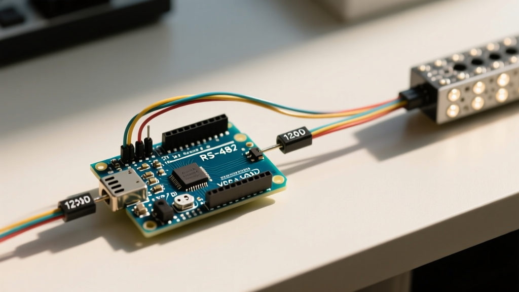
- Up to 1000 meters: Abandon raw UART. Use an RS-485 transceiver module (e.g., MAX485 chip modules, ~$1.50 each). RS-485 uses differential signaling, completely rejecting common-mode noise, making it the industrial standard for connecting microcontrollers over long distances.
Troubleshooting Matrix
| Symptom | Probable Cause | Actionable Fix |
|---|---|---|
| Pi receives random gibberish characters | Baud rate mismatch or Linux console spam | Verify both ends use identical baud rates. Run raspi-config to disable the serial login shell. |
Python throws Permission denied: '/dev/serial0' |
User lacks dialout group permissions | Run sudo usermod -a -G dialout $USER and reboot the Pi. |
| Arduino receives nothing from Pi | TX/RX lines not crossed or Pi TX voltage too low | Ensure Pi TX goes to Arduino RX. Verify Pi is outputting 3.3V with a multimeter. |
| Data drops occur under high CPU load on Pi | Linux OS UART buffer overflow | Implement a handshake protocol (RTS/CTS) or increase the Python read buffer size and polling frequency. |
| Pi GPIO pin gets hot / Pi reboots randomly | 5V backfeed from Arduino TX without level shifting | Immediately disconnect. Install a BSS138 level shifter or a 2.2k/3.3k voltage divider on the Arduino TX line. |