
The Legacy of the HC-SR04 and Why Migrate in 2026
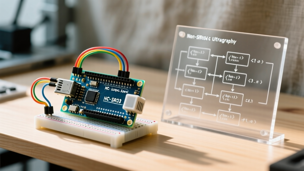
For over a decade, the HC-SR04 has been the undisputed 'hello world' of distance sensing in the maker community. Priced at roughly $1.50, this 40kHz ultrasonic transceiver paired with an Arduino Uno (ATmega328P) taught millions of engineers how to measure time-of-flight (ToF). However, as embedded projects mature into commercial IoT deployments and edge-AI robotics in 2026, the HC-SR04's architectural limitations become critical failure points.
The classic HC-SR04 suffers from a 15-degree beam width (causing multipath errors in tight enclosures), acoustic vulnerability (wind and machinery noise), and a strict 5V logic requirement. If you are migrating your stack from legacy 5V AVR Arduinos to modern 3.3V architectures like the ESP32-S3, Raspberry Pi Pico (RP2040), or Nordic nRF52, you must address both hardware voltage translation and software blocking routines. This guide provides a comprehensive migration path for upgrading your Arduino and HC-SR04 ecosystem.
Hardware Migration: Solving the 3.3V Logic Crisis
The most common mistake when migrating an HC-SR04 project to an ESP32 or RP2040 is connecting the sensor's Echo pin directly to the microcontroller's GPIO. The HC-SR04 requires a 5V supply to operate reliably, meaning its Echo pin outputs approximately 4.8V when HIGH. Feeding 4.8V into a 3.3V-tolerant GPIO will cause cumulative silicon degradation, leading to erratic pin behavior or permanent MCU failure.
Option A: The Passive Voltage Divider
For quick prototyping, a resistor voltage divider is the standard mitigation. By placing a 1kΩ resistor in series with the Echo pin and a 2kΩ resistor pulling down to GND, you step the 5V signal down to a safe 3.33V.
- R1 (Series): 1kΩ (Connect between HC-SR04 Echo and MCU GPIO)
- R2 (Shunt): 2kΩ (Connect between MCU GPIO and GND)
- Drawback: Adds parasitic capacitance, slightly softening the rising edge of the Echo pulse, which can introduce a 1-2mm measurement jitter at high frequencies.
Option B: Active Level Shifting (Production Grade)
For production PCBs, abandon resistors. Use a CD4050B non-inverting hex buffer powered at 3.3V, or a dedicated MOSFET-based level shifter (like the BSS138 circuit found on Adafruit's bi-directional shifters). This provides sharp, clean logic transitions essential for precise pulse-width measurement.
Sensor Upgrades: Beyond 40kHz Acoustics
If your application demands higher reliability, migrating away from the bare HC-SR04 module is highly recommended. Below is a comparison matrix of modern alternatives categorized by use-case.
| Sensor Model | Technology | Logic Level | Blind Spot | Max Range | Best Use Case | Est. Cost |
|---|---|---|---|---|---|---|
| HC-SR04 | 40kHz Ultrasonic | 5V Only | 2 cm | 400 cm | Indoor, 5V legacy MCUs | $1.50 |
| RCWL-1601 | 40kHz Ultrasonic | 3.3V / 5V | 2 cm | 500 cm | Native 3.3V ESP32/RP2040 projects | $2.80 |
| JSN-SR04T | 40kHz Ultrasonic | 5V Only | 20 cm | 600 cm | Outdoor, IP67 waterproof environments | $4.50 |
| Benewake TF-Luna | 850nm LiDAR ToF | 3.3V (UART/I2C) | 20 cm | 800 cm | High-speed, acoustic-noise immunity | $18.00 |
Note: If migrating to the Benewake TF-Luna, you shift from pulse-width timing to UART/I2C serial parsing, entirely eliminating acoustic interference from wind or industrial motors.
Software Migration: Eradicating Blocking Code
The standard Arduino implementation for ultrasonic sensing relies on the pulseIn() function. While easy to read, pulseIn() is a blocking routine. It halts all MCU operations while waiting for the Echo pin to go HIGH and then LOW.
The Blocking Bottleneck
Sound travels at roughly 343 meters per second. To measure a distance of 400cm, the sound wave must travel 8 meters round-trip. This takes approximately 23.3 milliseconds. In an RTOS environment (like FreeRTOS on the ESP32), a 23ms block starves background tasks, drops Wi-Fi packets, and ruins PID control loop timings for robotics.
The Upgrade: Interrupt-Driven Measurement
Modernize your firmware by migrating to hardware interrupts. Instead of waiting, you trigger the sensor and attach an interrupt to the Echo pin.
- Send a 10µs HIGH pulse to the Trigger pin.
- Attach a RISING interrupt to the Echo pin. Record
micros()asstartTime. - Inside the ISR, detach the RISING interrupt and attach a FALLING interrupt.
- On the FALLING edge, record
micros()asendTime. - Calculate duration and detach the FALLING interrupt.
This non-blocking approach reduces CPU overhead to near zero, allowing your MCU to handle wireless telemetry and motor control concurrently.
Environmental Calibration: Temperature Compensation
A frequently overlooked edge case in ultrasonic migration is thermal drift. The speed of sound is not a constant; it is highly dependent on ambient temperature. According to thermodynamic principles of the speed of sound, the velocity in dry air is calculated as:
v ≈ 331.3 + (0.606 × T)
Where v is velocity in m/s, and T is temperature in °C.
If your system is calibrated at 20°C (343.4 m/s) but deployed in an unheated warehouse at 0°C (331.3 m/s), your distance calculations will carry a 3.5% error. On a 4-meter measurement, this equates to a 14cm discrepancy—enough to crash a mobile robot into a wall.
Migration Action: Integrate a cheap I2C temperature sensor (like the BME280 or DS18B20) into your I/O loop. Dynamically update your distance multiplier in the firmware based on real-time thermal readings.
Real-World Failure Modes & Debugging Checklist
When upgrading or migrating HC-SR04 circuits, engineers frequently encounter 'ghost readings' (random 0cm or max-range spikes). Before blaming the MCU, check these hardware-level failure modes:
- Missing Decoupling Capacitor: The HC-SR04 draws sudden current spikes when firing the transducers. Without a 100nF ceramic capacitor placed directly across the VCC and GND pins on the sensor, voltage sag causes the internal comparator to misfire. Fix: Solder a 100nF cap directly to the sensor header.
- Breadboard Crosstalk: Long jumper wires on solderless breadboards act as antennas, picking up EMI from nearby DC motors or switching regulators. Fix: Use twisted-pair wiring for the Trigger and Echo lines, or migrate to a soldered protoboard.
- Acoustic Multipath: In PVC pipes or narrow corridors, the 15-degree beam bounces off the walls, returning a longer path-length echo. Fix: Line the enclosure walls with acoustic dampening foam, or upgrade to a narrower-beam LiDAR sensor.
Summary
Migrating your Arduino and HC-SR04 setup is not just about changing microcontrollers; it requires a holistic review of voltage tolerances, timing architectures, and environmental physics. By implementing active level shifting, adopting non-blocking interrupt routines, and considering modern alternatives like the RCWL-1601 or TF-Luna, you can transform a fragile hobbyist circuit into a robust, production-ready 2026 sensing node.