
Why Choose Modbus RTU Over Standard UART?
When building distributed sensor networks or industrial control panels, standard UART serial communication quickly hits a wall. Traditional RX/TX lines are single-ended, making them highly susceptible to electromagnetic interference (EMI) and limiting cable runs to roughly 15 meters. By implementing Modbus on Arduino via an RS485 physical layer, you transition to differential signaling. This allows data transmission over distances up to 1,200 meters while rejecting common-mode noise.
Modbus RTU (Remote Terminal Unit) is the application-layer protocol that sits on top of RS485. It uses a master-slave (or client-server) architecture where a single master polls multiple slaves for data. According to the Modbus Organization Protocol Specifications, RTU is the most widely used industrial protocol due to its high data density and minimal overhead compared to Modbus TCP or ASCII.
2026 Bill of Materials & Hardware Selection
To build a robust Modbus RTU network, you need the right transceivers. While the classic MAX485 is ubiquitous, it is strictly a 5V component. If you are using 3.3V microcontrollers like the Arduino Nano 33 IoT or ESP32, you must use a MAX3485 or SP3485 to avoid logic level damage and excessive EMI.
| Component | Model / Specification | Est. Price (2026) | Notes |
|---|---|---|---|
| Microcontroller | Arduino Uno R4 Minima | $27.50 | Renensas RA4M1 core, excellent hardware serial buffers. |
| RS485 Transceiver | HW-519 MAX485 Module | $1.80 | Standard 5V TTL to RS485 breakout board. |
| Termination Resistor | 120Ω 1/4W Carbon Film | $0.05 | Required at the physical ends of the bus. |
| Cabling | Belden 3106A (or Cat5e) | $1.20 / ft | Twisted pair is mandatory for noise rejection. |
| Isolation Module | ISO3082DW Breakout | $8.50 | Optional but recommended for industrial motor environments. |
Hardware Wiring: MAX485 to Arduino Uno
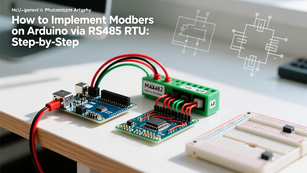
The most common point of failure in DIY Modbus implementations is incorrect handling of the half-duplex control pins. The MAX485 module features Driver Enable (DE) and Receiver Enable (RE) pins. Because RS485 is half-duplex (data flows in only one direction at a time), you must toggle these pins to switch between transmitting and listening.
Pro Tip: Solder a jumper wire between the DE and RE pins on the HW-519 module. This allows you to control both transmit and receive states with a single Arduino digital pin.
Pinout Mapping Table
| MAX485 Pin | Arduino Uno R4 Pin | Function & Configuration |
|---|---|---|
| VCC | 5V | Power supply. Do not connect to 3.3V on standard MAX485. |
| GND | GND | Common ground reference. Must be shared across all nodes. |
| RO (Receive Out) | RX (Pin 0) | Serial data from transceiver to Arduino. |
| DI (Data In) | TX (Pin 1) | Serial data from Arduino to transceiver. |
| DE / RE | Pin 8 | Direction control. HIGH = Transmit, LOW = Receive. |
| A (+) | Bus Wire A | Non-inverting differential data line. |
| B (-) | Bus Wire B | Inverting differential data line. |
Software Implementation: Master and Slave Nodes
For generic Arduino boards, the ModbusMaster library by Doc Walker remains the gold standard for master nodes in 2026, while the ModbusRTU library (by smarmengol) is excellent for slave configurations. Install both via the Arduino Library Manager.
1. The Master Node Logic (Polling)
The master node is responsible for initiating all communication. It sends a request frame containing the Slave ID, Function Code (e.g., 0x03 for Read Holding Registers), starting address, and quantity. Below is the core logic flow for reading two registers from Slave ID 1.
#include <ModbusMaster.h>
ModbusMaster node;
const int DE_RE_PIN = 8;

void preTransmission() { digitalWrite(DE_RE_PIN, HIGH); }
void postTransmission() { digitalWrite(DE_RE_PIN, LOW); }

void setup() {
  pinMode(DE_RE_PIN, OUTPUT);
  Serial.begin(9600);
  node.begin(1, Serial); // Slave ID 1
  node.preTransmission(preTransmission);
  node.postTransmission(postTransmission);
}

void loop() {
  uint8_t result = node.readHoldingRegisters(0, 2);
  if (result == node.ku8MBSuccess) {
    uint16_t sensorVal = node.getResponseBuffer(0);
  }
  delay(100);
}
2. The Slave Node Logic (Responding)
The slave node passively listens to the bus. When it detects its own ID, it processes the request and replies. The critical E-E-A-T detail here is the inter-frame delay. The Modbus RTU specification dictates that a frame boundary is recognized by a silent interval of at least 3.5 character times. At 9600 baud, one character (11 bits) takes ~1.14ms. Therefore, your slave must wait roughly 4ms of silence before assuming a message is complete. Modern libraries handle this via hardware serial idle interrupts, but if you are writing bare-metal code, failing to implement this 3.5-character silence rule is the #1 cause of CRC framing errors.
Critical RS485 Network Design Rules
Implementing Modbus on Arduino isn't just about code; the physical layer topology dictates your success. Follow these Texas Instruments RS-485 Design Guidelines to prevent phantom data and bus collisions.
- Termination: Place a 120Ω resistor across the A and B lines at the first and last physical nodes on the cable run. Do not terminate intermediate nodes. This prevents signal reflections that corrupt the CRC checksum.
- Failsafe Biasing: When no node is transmitting, the RS485 bus floats, making it an antenna for ambient noise. Use a 560Ω pull-up resistor to VCC on the A line, and a 560Ω pull-down resistor to GND on the B line. This biases the idle state to a logical '1' (Mark), preventing the master UART from receiving garbage bytes during bus idle times.
- Stub Length: The drop cable (stub) from the main twisted pair trunk to your Arduino MAX485 module must be kept under 0.3 meters (1 foot). Long stubs cause impedance discontinuities and signal degradation.
- Daisy Chain Topology: RS485 must be wired in a linear daisy chain or bus topology. Star topologies create severe reflection issues at the central junction.
Troubleshooting Common Modbus Failures
When your Arduino Modbus network fails, the ModbusMaster library returns specific hex error codes. Use this diagnostic matrix to isolate the fault.
| Error Code | Meaning | Root Cause & Solution |
|---|---|---|
| 0xE0 | Timeout | Slave is offline, baud rate mismatch, or DE/RE pin is stuck HIGH (master is talking to itself). Check wiring and verify slave ID. |
| 0xE1 | Invalid Slave ID | The master received a response, but the ID didn't match the request. Usually caused by severe bus noise corrupting the address byte. |
| 0xE2 | Invalid Function | Slave does not support the requested function code (e.g., trying to write to a read-only input register). |
| 0xE8 | Invalid CRC | The message arrived, but the checksum failed. Add termination resistors, check for untwisted cables, or implement galvanic isolation. |
Dealing with Ground Loops in Industrial Settings
If you are deploying your Arduino Modbus nodes near VFDs (Variable Frequency Drives) or heavy AC contactors, standard MAX485 modules will likely fail due to ground potential differences. The RS485 standard allows for a common-mode voltage range of -7V to +12V. If the ground potential between two nodes exceeds this, the transceiver will latch up or burn out. In these scenarios, upgrade to an isolated RS485 transceiver like the ISO3082, or use digital isolators (e.g., ISO7741) between the Arduino UART pins and a standard MAX485. This breaks the ground loop while preserving the differential data integrity.
Frequently Asked Questions
Can I mix 3.3V and 5V Arduinos on the same RS485 bus?
Yes, but with caveats. The RS485 bus itself operates on differential voltages that easily bridge logic families. However, the TTL side (RX/TX/DE/RE) must match the microcontroller. Use a MAX3485 module for 3.3V boards (like the Nano 33 BLE) and a standard MAX485 for 5V boards (like the Uno R4). They will communicate perfectly on the same A/B twisted pair.
How many Modbus slaves can one Arduino master support?
The Modbus protocol supports up to 247 unique slave addresses (1-247). However, the physical RS485 bus limit is typically 32 unit loads for standard transceivers. If you need more than 32 nodes, use transceivers with a 1/8th unit load rating (like the MAX1487), which allows up to 256 nodes on a single bus segment without a repeater.