
The Anatomy of an Arduino and LED Strip Failure
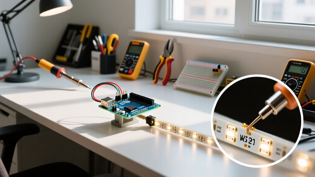
Integrating an Arduino and LED strip (such as WS2812B, SK6812, or modern high-density COB variants) remains one of the most rewarding projects in the maker space. However, as we move into 2026, the shift toward 3.3V microcontrollers like the ESP32-S3 and the increasing pixel density of addressable strips have introduced new layers of electrical complexity. When your pixels flicker, display random colors, or fail to illuminate past a certain point, the root cause is rarely your C++ sketch. It is almost always an electrical bottleneck.
Error diagnosis in addressable lighting requires a systematic approach to power delivery, logic level translation, and signal integrity. Below is a comprehensive diagnostic framework to isolate and resolve the most common hardware failures in your setup.
Symptom-to-Solution Diagnostic Matrix
Before reaching for a multimeter, match your visual symptoms to this diagnostic matrix to narrow down the probable failure domain.
| Visual Symptom | Probable Electrical Cause | Diagnostic Action |
|---|---|---|
| Strip flickers white or random colors | Logic level mismatch (3.3V MCU to 5V Data In) | Measure data pin voltage; insert SN74AHCT125 level shifter. |
| Colors shift to red/pink at the far end | Severe voltage drop on the 5V rail | Measure voltage at the last pixel; add secondary power injection. |
| Only the first 1-3 pixels light up | Missing shared ground or broken internal data trace | Verify continuity between MCU GND and Strip GND. |
| Entire strip glitches when motors/relays trigger | Back-EMF noise or insufficient bulk capacitance | Install 1000µF electrolytic capacitor at power entry points. |
Power Starvation: The Voltage Drop Killer
The most pervasive error in any Arduino and LED strip build is underestimating current draw and wire resistance. A standard 5-meter strip of 60 LEDs/meter WS2812B pixels draws approximately 18 Amps at full white (60mA per LED × 300 LEDs).
Calculating Wire Gauge Limits
Many beginners use the thin 22 AWG jumper wires included in starter kits for power distribution. This is a critical error. A 22 AWG copper wire has a resistance of roughly 16 mΩ per foot. Pushing 5A through a 3-foot run of 22 AWG wire results in a voltage drop of nearly 0.5V. Since WS2812B pixels require a minimum of 3.5V to operate reliably, a 5V source dropping to 4.5V at the strip's input will cause immediate brownouts and data corruption.
- Under 3 Amps: 20 AWG wire is acceptable for short runs (under 1 meter).
- 3 to 10 Amps: Use 18 AWG silicone wire for power injection.
- Over 10 Amps: Step up to 16 AWG or 14 AWG, and inject power at both ends of the strip, or every 2 meters for high-density 144 LEDs/m strips.
The 1000µF Capacitor Rule
Addressable LEDs do not draw current linearly; they pulse at high frequencies. When a strip transitions from black to full white, the sudden inrush current can cause a momentary voltage sag that resets the microcontroller or corrupts the data latch. According to the Adafruit NeoPixel Überguide, you must place a 1000µF, 6.3V (or higher) electrolytic capacitor across the VCC and GND lines as close to the strip's first pixel as possible. This acts as a local energy reservoir to absorb transient spikes.
The 3.3V vs 5V Logic Level Trap
With the maker community largely migrating to 3.3V architectures like the ESP32 and Raspberry Pi Pico, logic level mismatch has become the leading cause of intermittent flickering. The WS2812B and SK6812 datasheets specify that the Input High Voltage ($V_{IH}$) must be at least $0.7 \times V_{DD}$. If your strip is powered by 5V, the data line must reach a minimum of 3.5V to register a logical HIGH.
A 3.3V microcontroller pin outputs exactly 3.3V, which falls short of the 3.5V threshold. While some strips might "tolerate" this due to manufacturing variances, it results in marginal noise margins, leading to random color shifts and dropped frames.
The "First Pixel" Myth: A common forum workaround suggests wiring the data line through the first pixel's DOUT pin, relying on the first LED to act as a 5V level shifter for the rest of the strip. While this sometimes works because the first LED's internal circuitry outputs a cleaner 5V signal, it is not guaranteed by the datasheet and places undue thermal and electrical stress on that single diode. Always use a dedicated level shifter.
Choosing the Right Level Shifter
Not all level shifters are created equal. The bidirectional MOSFET-based level shifters (often utilizing the BSS138 transistor) sold on breakout boards are designed for slow protocols like I2C (400kHz). They cannot handle the 800kHz to 2MHz PWM frequencies required by addressable LED data lines, resulting in rounded signal edges and data corruption. As detailed in the SparkFun Logic Levels Tutorial, you must use a high-speed, unidirectional logic IC. The SN74AHCT125 or 74HCT245 are the industry standards for this task, cleanly translating 3.3V logic to 5V at high speeds without signal degradation.
Signal Integrity and the Data Line Resistor
Long data wires act as antennas, picking up electromagnetic interference (EMI) from nearby AC mains, switching power supplies, or Wi-Fi antennas. Furthermore, the fast rise and fall times of the microcontroller's GPIO pins can cause high-frequency ringing when driving the capacitive load of the LED strip's data input.
To mitigate this, always solder a 300Ω to 500Ω through-hole resistor directly onto the data wire, as close to the strip's DIN pad as possible. This resistor forms a low-pass filter with the trace capacitance, dampening ringing and protecting the first pixel's sensitive data input from electrostatic discharge (ESD) and voltage spikes.
Multimeter Triage Protocol
When visual inspection fails, follow this strict 4-step multimeter diagnostic flow to isolate the fault:
- Verify the Source Voltage: Set your DMM to DC Voltage. Measure directly at the output terminals of your 5V power supply. It should read between 5.0V and 5.2V. If it reads below 4.8V under load, your power supply is overloaded or failing.
- Measure the Rail Drop: Keep the black probe on the power supply's GND terminal. Move the red probe to the 5V copper pad at the far end of the LED strip. If the voltage reads below 4.2V, you have a severe voltage drop and must add a secondary power injection wire.
- Check Ground Continuity: Power down the system. Set the DMM to continuity mode (the diode/beep symbol). Place one probe on the Arduino GND pin and the other on the LED strip GND pad. A reading of less than 1Ω confirms a solid shared ground. If it reads OL (Open Loop), your data signals have no reference path, and the strip will not function.
- Probe the Data Signal: Switch the DMM to AC Voltage (or use an oscilloscope if available). While the strip is running an animation, probe the data line after the 300Ω resistor. You should see a fluctuating AC voltage (typically 1.5V to 2.5V RMS), indicating that the MCU is actively transmitting PWM data. If it reads 0V, the issue is isolated to the microcontroller pin configuration or a broken trace.
Summary
Successful error diagnosis in an Arduino and LED strip project requires moving beyond code and understanding the physical realities of high-current, high-frequency digital circuits. By properly sizing your wire gauges, respecting the 3.3V/5V logic threshold with an SN74AHCT125, and maintaining strict ground continuity, you can eliminate 95% of the flickering and color-shifting errors that plague custom lighting installations.