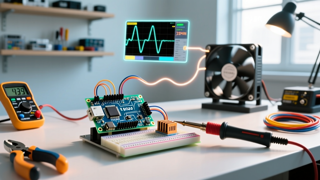

The Anatomy of a Closed-Loop Arduino Computer Fan Controller
Building a custom arduino computer fan controller is a staple project for thermal management enthusiasts and PC modders. However, transitioning from a basic 12V relay toggle to a closed-loop, temperature-responsive PWM system introduces a host of hardware and firmware edge cases. In 2026, with high-static-pressure 120mm and 140mm PC fans pushing upwards of 2.5A at peak RPM, the power stage and signal integrity of your microcontroller circuit are under more stress than ever.
When your fans stall, emit an audible high-pitched whine, or report erratic RPM data in the serial monitor, the issue rarely lies in the basic logic of your sketch. Instead, it stems from a misunderstanding of the Intel 4-Wire PWM specification, logic-level MOSFET gate capacitance, or interrupt starvation. This guide provides a deep-dive diagnostic framework for the most common hardware and firmware faults encountered in DIY fan controllers.
Critical Fault Matrix: Symptoms vs. Root Causes
Before grabbing an oscilloscope, map your system's behavior to this diagnostic matrix to isolate the failing subsystem.
| Symptom | Probable Root Cause | Diagnostic Tool | Hardware / Firmware Fix |
|---|---|---|---|
| Audible high-pitched whine from fan motor | PWM frequency is ~490Hz instead of 25kHz | Logic Analyzer / Audio FFT | Reconfigure Timer1 registers for 25kHz output |
| MOSFET overheating (>60°C) at mid-range RPM | Using standard MOSFET instead of true Logic-Level | Thermal Camera / Multimeter | Swap to IRLB8721PBF or add a dedicated gate driver |
| RPM reads exactly double or half of actual speed | Interrupt edge mismatch or ignoring 2-pulse/rev spec | Serial Monitor / Strobe Light | Change attachInterrupt to FALLING edge |
| Fan randomly stalls when temp sensor polls | I2C bus lockup starving the main loop | Serial Debug / Watchdog Timer | Implement I2C bus watchdog and hardware failsafe |
| MOSFET fails catastrophically (shorts 12V to GND) | Inductive flyback spike exceeding Vds breakdown | Visual Inspection / Datasheet | Install a fast-recovery Schottky flyback diode |
Deep Dive 1: PWM Signal Degradation & Acoustic Whine
The 25kHz vs 490Hz Dilemma
The most frequent complaint among beginners building an arduino computer fan controller is a severe, high-pitched acoustic whine emanating from the PC case. This is caused by driving the fan's PWM input with the Arduino's default analogWrite() frequency. On an Arduino Uno or Nano, pins 5 and 6 operate at roughly 980Hz, while pins 9, 10, and 11 operate at roughly 490Hz. According to the Intel 4-Wire PWM Controlled Fans specification, standard PC fans require a 25kHz PWM signal to operate silently and maintain stable low-RPM commutation.
When fed a 490Hz signal, the fan's internal commutation IC struggles to switch the stator coils cleanly, resulting in micro-vibrations that translate into audible noise. Furthermore, low-frequency PWM destroys the fan's ability to hold a steady low RPM, often causing the motor to stall entirely below 40% duty cycle.
The Firmware Fix: Timer1 Manipulation
To resolve this, you must bypass the standard Arduino wiring library and manipulate the ATmega328P's Timer1 registers directly, or use a trusted wrapper like the TimerOne library. By setting the timer prescaler and ICR1 (Input Capture Register) correctly, you can force pins 9 and 10 to output a precise 25kHz square wave. Note that doing this will break standard functions like delay() if they rely on Timer1, so plan your timing architecture around millis() or Timer2.
Deep Dive 2: Power Stage & MOSFET Gate Charge Bottlenecks
The 'Logic-Level' Misconception
A fatal error in many DIY controller schematics is the selection of the power MOSFET. Many makers reach for the IRFZ44N or IRLZ44N because they are cheap and widely available. While the 'L' in IRLZ44N implies 'Logic Level', a review of the Infineon datasheet reveals that its RDS(on) (drain-source on-resistance) is only guaranteed at a Gate-to-Source Voltage (Vgs) of 10V. When driven directly from an Arduino's 5V digital pin, the MOSFET operates in its linear (ohmic) region rather than fully saturating. This results in massive power dissipation as heat, often melting breadboards or triggering thermal shutdown.
The 2026 Standard: Use the IRLB8721PBF or the STP16NF06L. The IRLB8721PBF boasts an exceptionally low RDS(on) of roughly 2.4mΩ at Vgs = 4.5V, meaning it will run ice-cold even when switching 12V at 5A without a heatsink. Priced at around $1.50 per unit, it is the undisputed king of DIY 5V-driven fan controllers.
Gate Resistor Sizing
Do not connect the Arduino GPIO pin directly to the MOSFET gate. The gate acts as a capacitor (Gate Charge, Qg). Charging this capacitor instantly draws a massive current spike that can degrade or destroy the ATmega328P's output driver over time. Always place a 100Ω to 220Ω gate resistor in series. Additionally, place a 10kΩ pull-down resistor between the Gate and Source (GND) to ensure the fan turns off if the Arduino reboots or the GPIO pin floats during initialization.
Deep Dive 3: Tachometer (RPM) Feedback Failures
Open-Collector Pull-Up Sizing
The yellow (or sometimes blue) tachometer wire on a 4-pin PC fan is an open-collector output. It pulls the line to GND with every half-revolution of the motor but cannot drive the line HIGH. If you connect this directly to an Arduino input pin without a pull-up resistor, the pin will float, picking up electromagnetic interference (EMI) from the switching MOSFET and reporting RPMs in the tens of thousands.
While the internal Arduino INPUT_PULLUP (approx. 20kΩ - 50kΩ) can sometimes work, the weak pull-up combined with parasitic capacitance on long wires causes the rising edge to slope slowly, resulting in missed or double-triggered interrupts. Best Practice: Use an external 4.7kΩ or 10kΩ resistor tied directly from the tachometer pin to the Arduino's 5V rail, and configure the pin as standard INPUT.
Interrupt Starvation & Edge Detection
Most PC fans output two pulses per revolution. If your serial monitor shows exactly double the actual RPM, your math is likely missing a division by 2. However, if the RPM data is erratic, the issue is often interrupt edge configuration. Using CHANGE in Arduino's attachInterrupt function triggers on both the falling and rising edges. Because the rising edge is dependent on your pull-up resistor's RC time constant, it can jitter. Always configure the interrupt to trigger on FALLING edge only for rock-solid tachometer readings.
Thermal Runaway & Flyback Diode Selection
Critical Warning: A PC fan is an inductive load. When the MOSFET switches off, the collapsing magnetic field in the fan's stator coils generates a massive reverse voltage spike (inductive kickback). Without a flyback diode, this spike will exceed the MOSFET's Vds breakdown voltage, instantly punching a hole through the silicon and permanently shorting 12V to GND.
Many tutorials recommend the standard 1N4007 rectifier diode for flyback protection. This is a dangerous mistake for PWM applications. The 1N4007 has a reverse recovery time (trr) of roughly 30µs. At a 25kHz PWM frequency, the switching period is only 40µs. The diode is too slow to clamp the spike before the next cycle begins, leading to localized heating and eventual MOSFET failure.
The Fix: Use a Schottky diode such as the 1N5819 (1A) or 1N5822 (3A). Schottky diodes have virtually zero reverse recovery time and a lower forward voltage drop, clamping the inductive spike instantly and safely dissipating the stored energy back into the fan's loop. They cost less than $0.15 each and are mandatory for any reliable arduino computer fan controller.
Firmware Debugging: I2C Sensor Lockups
In a closed-loop system, your Arduino reads a temperature sensor (like a BME280 or TMP36) to adjust the PWM duty cycle. If you are using an I2C sensor, you are vulnerable to bus lockups. If EMI from the fan motor or a loose breadboard connection causes the SDA line to be pulled LOW while the Arduino is clocking, the Wire library will hang indefinitely waiting for a clock stretch that never comes.
When the sketch hangs, the PWM output freezes at its last duty cycle. If the system was under heavy load, the fans will remain at 100% indefinitely; if it was idling, the fans will stall at 0%, potentially overheating your PC components.
Implementing a Failsafe
- Hardware Watchdog: Enable the ATmega328P's internal Watchdog Timer (WDT) set to 2 seconds. Reset the WDT at the end of every successful
loop()iteration. If an I2C hang occurs, the WDT will force a hardware reset. - Safe-State Default: In your
setup()function, before initializing the I2C bus, immediately set the PWM pins to a 70% duty cycle. This ensures that if the MCU crashes and reboots, the fans are already spinning at a safe, high-airflow state during the boot sequence. - Software Timeout: Wrap your
Wire.requestFrom()calls in a custom timeout function that manually resets the I2C peripheral registers if the bus fails to respond within 50 milliseconds.
Summary Checklist for Bench Testing
Before installing your controller into a PC chassis, run through this bench-test protocol using a cheap bench power supply and a logic analyzer:
- Verify PWM Frequency: Probe the gate of the MOSFET with a logic analyzer. Confirm the frequency is exactly 25,000Hz.
- Check Gate Drive Voltage: Measure the voltage at the MOSFET gate relative to source while the Arduino is outputting HIGH. It must be >4.5V.
- Validate Tachometer Pull-Up: Measure the tachometer wire with an oscilloscope. The rising edge should be sharp (under 2µs), not a slow curve.
- Inductive Spike Test: Probe the drain of the MOSFET. When the PWM signal goes LOW, the voltage spike should be clamped to roughly 12.5V - 13V. If you see spikes exceeding 20V, your flyback diode is missing, incorrectly oriented, or too slow.
- Thermal Soak: Run the fan at a 50% duty cycle for 15 minutes. The MOSFET should remain below 45°C to the touch.
By addressing the acoustic, electrical, and firmware edge cases outlined above, your DIY fan controller will rival commercial enthusiast hubs in both reliability and acoustic performance.