
Serial to Arduino: The Ultimate Quick Reference FAQ
Serial communication remains the backbone of microcontroller debugging, sensor integration, and inter-device networking. Whether you are routing UART data from an ESP32 to an Arduino Mega, or interfacing a legacy RS-232 industrial PLC with an Arduino Uno, understanding the electrical and protocol-level nuances is critical. This quick reference guide addresses the most frequent engineering questions, wiring pitfalls, and protocol edge cases surrounding serial to Arduino connections in modern maker and professional environments.
Core Specifications Quick-Reference Table
| Parameter | 5V AVR (Uno/Nano/Mega) | 3.3V ARM (Zero/ESP32/Teensy) | Engineering Notes |
|---|---|---|---|
| Logic HIGH (V_IH) | 3.0V to 5.5V | 2.0V to 3.6V | Exceeding V_IH max will destroy 3.3V GPIO pins. |
| Hardware UARTs | 1 (Uno), 4 (Mega 2560) | 2 to 6 (depending on SoC) | Hardware UARTs have dedicated FIFO buffers. |
| Hardware Buffer Size | 64 Bytes (RX/TX) | 128 to 256 Bytes | Overflow results in silent data loss (DOR flag). |
| Max Reliable Baud | 115,200 (Hardware) | 921,600+ (Hardware) | SoftwareSerial caps reliably at 38,400 on AVR. |
Frequently Asked Questions (FAQ)
1. How do I correctly wire a USB-to-Serial adapter to an Arduino?
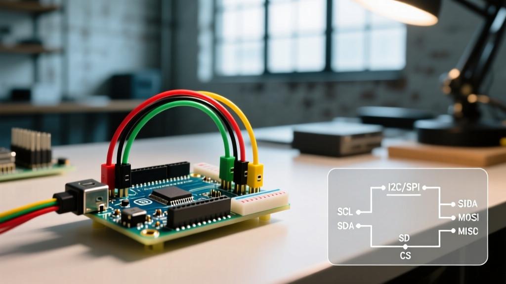
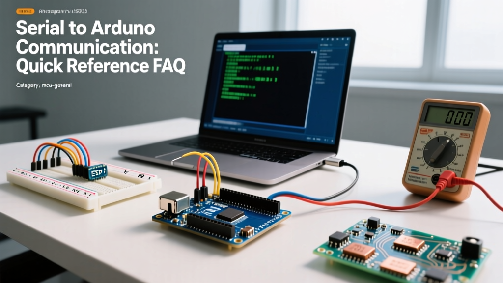
When bypassing the onboard USB interface (e.g., programming a barebones ATmega328P on a breadboard via an FTDI FT232RL or CH340G adapter), you must cross the data lines and share a common ground. Wire the adapter's TX to the Arduino's RX, and the adapter's RX to the Arduino's TX. Crucially, the GND pins must be connected; without a shared ground reference, the voltage differential will cause erratic data corruption.
The Auto-Reset Trick: To enable automatic sketch uploading without manually pressing the reset button, wire a 0.1µF ceramic capacitor between the adapter's DTR (Data Terminal Ready) pin and the ATmega328P's RESET pin. When the IDE opens the serial port, the DTR line drops low, and the capacitor creates a brief negative spike on the RESET line, triggering the bootloader precisely when the upload begins.
2. Why is my serial to Arduino data displaying as garbage characters?
Garbage output (e.g., `` or random ASCII symbols) in the Serial Monitor almost always stems from one of two issues:
- Baud Rate Mismatch: Your sketch initializes
Serial.begin(115200), but the IDE Serial Monitor dropdown is set to 9600. The receiver samples the bits at the wrong intervals, interpreting the voltage transitions as entirely different characters. - Logic Level Violation: You are transmitting 5V TTL serial from an Arduino Uno into the 3.3V RX pin of an ESP32 or Arduino Zero. The overvoltage forward-biases the microcontroller's internal ESD protection diodes, clamping the signal and severely distorting the square wave edges, leading to bit errors. Always use a BSS138 MOSFET-based bidirectional level shifter when bridging 5V and 3.3V domains.
3. What are the limitations of SoftwareSerial vs. Hardware Serial?
On 8-bit AVR boards like the Uno, pins 0 and 1 are tied to the single hardware USART. If you need a second serial port (e.g., for a GPS module), developers often turn to the SoftwareSerial library. However, this comes with severe constraints:
Expert Warning:
SoftwareSerialrelies on pin-change interrupts and blocking delay loops to sample incoming bits. On a 16MHz ATmega328P, receiving a single byte at 9600 baud takes over 1 millisecond of pure CPU blocking time. At 115200 baud, the CPU cannot keep up with the bit-rate if any other interrupts (like Timer0 formillis()) fire, resulting in dropped bytes. For reliable multi-port serial in 2026, migrate to ARM-based boards like the Teensy 4.1 (8 hardware UARTs) or ESP32-S3.
4. How far can I run a serial to Arduino UART cable?
Standard TTL UART is an unbalanced, single-ended signaling protocol. It is highly susceptible to capacitive loading and electromagnetic interference (EMI). Using standard 24AWG twisted-pair wire:
- At 9600 Baud: Maximum reliable distance is approximately 15 meters (50 feet).
- At 115,200 Baud: Limit the cable run to 1.5 meters (5 feet). Higher frequencies suffer from edge-rounding due to cable capacitance, causing the receiver to misinterpret bit boundaries.
For long-distance serial to Arduino communication, abandon TTL UART and use an RS-485 transceiver (like the MAX485). RS-485 uses differential signaling, allowing reliable data transmission up to 1,200 meters at lower baud rates.
Troubleshooting Matrix: Serial to Arduino Errors
| Symptom | Probable Cause | Exact Fix |
|---|---|---|
| Code uploads fail with 'Programmer not responding' | Serial TX/RX lines crossed incorrectly, or external hardware holding RX HIGH. | Verify TX->RX crossover. Disconnect external sensors from Pin 0 (RX) during upload. |
| Data is received, but intermittent bytes are missing | Hardware buffer overflow (64-byte limit exceeded while MCU is busy). | Implement a non-blocking ring buffer or reduce main loop blocking delays. |
| Arduino randomly resets when serial cable is plugged in | USB hub power sag or DTR line toggling unexpectedly. | Use a powered USB hub. Add a 10k pull-up resistor on the RESET line. |
| ESP32 prints boot garbage on startup | ROM bootloader prints at 74880 baud before user sketch starts. | Ignore it, or use a logic analyzer to filter. Normal ESP32 hardware behavior. |
Advanced Edge Cases & Pro Tips
RS-232 vs. TTL Serial: The Voltage Trap
A frequent point of failure when connecting legacy industrial equipment to an Arduino is confusing TTL UART with RS-232. Standard Arduino pins operate on TTL logic (0V for LOW, 5V or 3.3V for HIGH). RS-232, commonly found on older PLCs and PC COM ports, uses inverted voltage levels: -3V to -15V represents a logical HIGH, and +3V to +15V represents a logical LOW. Connecting an RS-232 cable directly to an Arduino's RX pin will instantly destroy the microcontroller's GPIO due to overvoltage. You must use a MAX232 or MAX3232 transceiver IC to convert the RS-232 voltage levels to safe TTL levels before feeding them into the Arduino.
Handling Floating RX Pins
If your Arduino is configured to listen for serial data, but the external device is powered off or disconnected, the RX pin is left 'floating'. In high-EMI environments (like near stepper motors or relays), the floating RX pin can act as an antenna, picking up noise. The hardware UART will interpret this noise as incoming data, filling the 64-byte buffer with garbage and triggering false serial events. Always use a 10kΩ pull-up resistor from the RX pin to VCC to hold the line in a stable HIGH (idle) state when disconnected.
Authoritative References
For deeper protocol analysis and library-specific implementations, consult the following foundational resources:
- Arduino Official Serial Reference - Comprehensive documentation on hardware serial methods and buffer management.
- SparkFun Serial Communication Tutorial - Excellent visual breakdowns of UART packet structures, parity bits, and stop bits.
- Arduino SoftwareSerial Library Docs - Official limitations and pin-interrupt mapping for AVR architectures.