
The Evolution of Arduino for LED Applications
Selecting the correct microcontroller is the most critical hardware decision in any lighting project. When evaluating an Arduino for LED control, makers often default to the classic ATmega328P-based boards. However, as addressable LEDs (like WS2812B NeoPixels and APA102 DotStars) and high-density matrices have become the standard in 2026, legacy boards frequently hit severe memory and timing bottlenecks. This compatibility guide breaks down the electrical, architectural, and logic-level requirements for driving everything from simple 5mm indicator LEDs to 5,000-pixel architectural installations.
Board Compatibility Matrix: 2026 Hardware Lineup
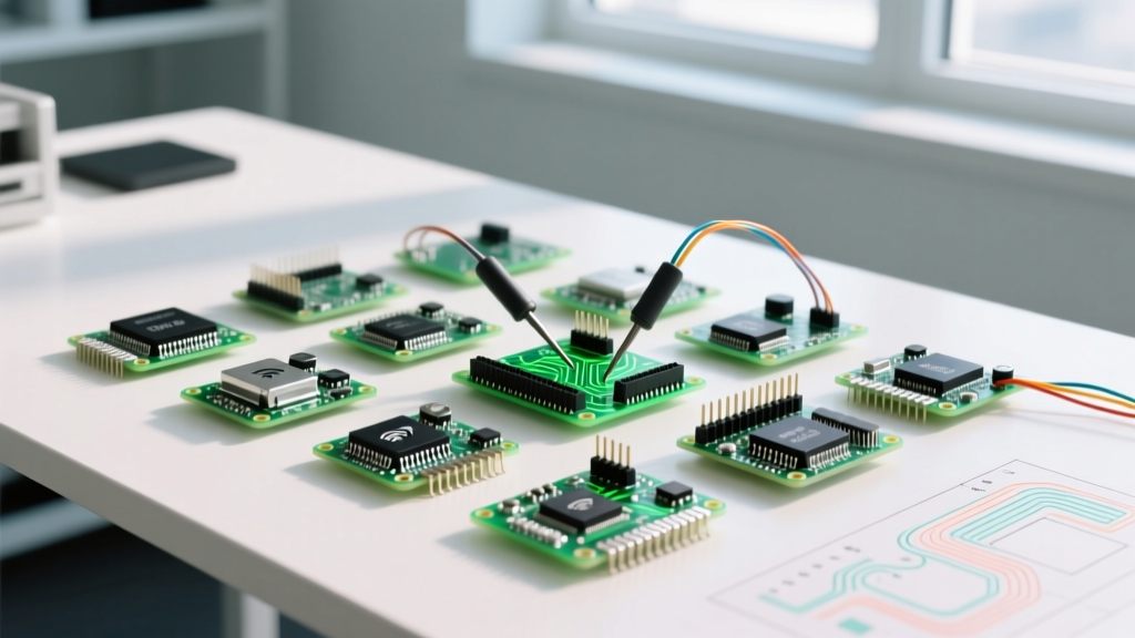
Before diving into the electrical engineering constraints, review this compatibility matrix comparing current mainstream development boards against specific LED topologies.
| Microcontroller Board | Logic Voltage | SRAM | Best LED Application | Approx. Price |
|---|---|---|---|---|
| Arduino Uno R4 Minima | 5V | 32 KB | Standard LEDs, <1000 WS2812B pixels | $19.99 |
| Arduino Nano ESP32 | 3.3V | 520 KB | Wi-Fi Sync, High-Res Matrices, WLED | $24.00 |
| Raspberry Pi Pico (RP2040) | 3.3V | 264 KB | PIO-Driven Flicker-Free Strips, POV | $4.00 |
| Adafruit Feather RP2040 Scorpio | 3.3V (5V shifted) | 264 KB | Native 8-Channel NeoPixel Output | $11.95 |
The SRAM Bottleneck: Addressable LED Memory Math
When driving addressable LEDs, the microcontroller must store the color state of every single pixel in its SRAM before transmitting the data stream. This is where many beginners fail when choosing an Arduino for LED matrices.
Calculating Memory Overhead
Most popular libraries, such as FastLED and Adafruit NeoPixel, require 3 bytes of SRAM per pixel (one byte each for Red, Green, and Blue). If you are using RGBW LEDs (like the SK6812), this jumps to 4 bytes per pixel.
- 100 Pixels (WS2812B): 300 bytes (Easily handled by legacy ATmega328P with 2KB SRAM)
- 500 Pixels (WS2812B): 1,500 bytes (Approaching the danger zone on ATmega328P; leaves almost no room for Wi-Fi buffers or complex math)
- 1,440 Pixels (144/m strip, 10 meters): 4,320 bytes (Impossible on ATmega328P; requires a 32-bit ARM Cortex-M0+ or ESP32)
According to the Arduino Uno R4 Minima Documentation, the upgraded Renesas RA4M1 processor includes 32KB of SRAM, effectively solving the memory bottleneck that plagued the older Uno R3 for large-scale LED art installations.
Logic Level Incompatibilities: The 3.3V vs 5V Problem
A pervasive edge case in modern maker projects involves pairing 3.3V microcontrollers (like the ESP32 or RP2040) with 5V addressable LEDs. The WS2812B datasheet specifies that a logical 'HIGH' on the data line must be at least 0.7 × VDD. For a 5V LED, that means the data signal must reach a minimum of 3.5V.
Expert Warning: Feeding a 3.3V data signal from an ESP32 directly into a 5V WS2812B strip will result in erratic flickering, random color flashing, or complete failure to initialize. While some LED batches are more tolerant than others, relying on out-of-spec voltage thresholds is a hallmark of unreliable commercial installations.
Hardware Solutions for Logic Shifting
If your chosen Arduino for LED control operates at 3.3V, you must implement a level shifter. Do not use the CD4050B or BSS138; they are too slow for the 800kHz pulse-width modulation required by WS2812B protocols. Instead, use the SN74AHCT125 or 74HCT245 logic level translator IC. These chips can cleanly step up a 3.3V GPIO signal to a 5V logic HIGH at speeds well over 50MHz, ensuring pristine data timing.
PWM Frequencies and High-Power Analog Dimming
For non-addressable, high-power LED strips (e.g., 12V or 24V single-color COB strips), microcontrollers rely on Pulse Width Modulation (PWM) to simulate analog dimming. The choice of board drastically affects the smoothness of the dimming curve and the potential for audible noise in the power supply.
Comparing PWM Architectures
- ATmega328P (Uno R3/Nano): Default PWM frequency is roughly 490Hz. This low frequency can cause visible flickering on high-speed camera sensors and may induce an annoying high-pitched whine in cheap 12V LED power supplies.
- RP2040 (Raspberry Pi Pico): Features highly configurable hardware PWM with frequencies extending past 100kHz. As detailed in the Raspberry Pi Pico RP2040 Datasheet, pushing the PWM frequency to 20kHz+ eliminates camera flicker entirely and pushes inductor noise out of the human hearing range.
MOSFET Selection: When driving 12V/24V strips via PWM, you must use a logic-level N-channel MOSFET. The classic IRF520 requires 10V on the gate to fully open, making it useless for 5V or 3.3V Arduinos. Always specify the IRLZ44N or PSMN2R0-30PL, which fully saturate at gate voltages as low as 2.5V, ensuring minimal heat dissipation and maximum current transfer to your LED strips.
Power Injection and Grounding Rules
No Arduino for LED guide is complete without addressing power distribution. Addressable LEDs draw massive current. A single WS2812B pixel drawing full white consumes roughly 60mA. A standard 5-meter strip of 60 LEDs/meter contains 300 pixels, pulling 18 Amps at 5V (90 Watts).
The Voltage Drop Phenomenon
Copper traces on flexible printed circuit boards (FPCBs) are thin. If you power a 5-meter strip from only one end, the voltage at the far end will drop below 4V, causing the LEDs to shift from white to red/pink and eventually shut down.
- Inject Power Every 50 Pixels: Run parallel power lines and solder them to the strip's VCC and GND pads every 2.5 meters (or every 50 pixels for high-density strips).
- Size Your Wiring Correctly: For a 60A master bus, 18 AWG wire will melt. You must use 10 AWG silicone wire for the main power injection harness from the supply to the distribution block.
- The Bulk Capacitor Rule: Always place a 1000µF to 2200µF electrolytic capacitor (rated for at least 6.3V, preferably 10V) directly across the VCC and GND terminals where the power enters the first pixel. This absorbs the initial inrush current and protects the microcontroller from brownout resets. The Adafruit NeoPixel Überguide heavily emphasizes this step to prevent catastrophic data-line backfeeding.
Troubleshooting Common Arduino LED Failures
Even with the correct board, environmental and electrical edge cases can disrupt your installation. Use this diagnostic checklist before rewriting your sketch.
- Symptom: The first LED is always yellow/green, but the rest are off.
Fix: You have a missing common ground. The GND pin of the Arduino must be tied directly to the GND of the LED power supply. Data signals require a shared reference voltage. - Symptom: LEDs flicker violently when Wi-Fi is enabled (ESP32 boards).
Fix: Wi-Fi transmission causes massive microsecond current spikes on the 3.3V rail, disrupting the CPU's strict timing loops. Switch to an RP2040 board utilizing Programmable I/O (PIO) to offload LED timing to a dedicated hardware state machine, freeing the main CPU to handle network interrupts. - Symptom: Random pixels at the end of the chain flicker.
Fix: Data signal degradation. Add a 300-ohm to 500-ohm resistor on the data line as close to the first LED's DIN pad as possible to dampen high-frequency signal ringing and reflections.
Final Verdict: Matching the Board to the Build
There is no single 'best' Arduino for LED projects; the ideal choice depends entirely on the pixel count and network requirements. For standalone, high-density art pieces requiring complex math and massive SRAM, the Raspberry Pi Pico (RP2040) offers unmatched value and PIO-driven stability. For IoT-connected architectural lighting where Wi-Fi is mandatory, the Arduino Nano ESP32 paired with a 74AHCT125 level shifter remains the industry standard in 2026. By respecting SRAM limits, logic thresholds, and power injection physics, you can scale your LED projects from a single desk lamp to a multi-story building facade without hardware failure.