
The 5V Hardware Limit: Why Direct Wiring Fries Your MCU
If you are learning how to measure voltage with Arduino, the very first rule is understanding the absolute maximum ratings of the microcontroller's analog-to-digital converter (ADC). On classic 5V boards like the Arduino Uno R3 or Nano (based on the ATmega328P), the analog pins (A0-A5) can only tolerate a maximum of 5.0V relative to ground. Applying 12V from a car battery or 24V from an industrial power supply directly to an analog pin will instantly destroy the internal clamping diodes and permanently kill the microcontroller.
To safely interface higher DC voltages with your Arduino, you must step down the voltage to a safe 0-5V range before it reaches the ADC pin. The most cost-effective, reliable, and universally used method for this is the passive resistor voltage divider.
The Math: Designing Your Voltage Divider
A voltage divider uses two resistors in series to create an output voltage ($V_{out}$) that is a precise fraction of the input voltage ($V_{in}$). According to SparkFun's electronics tutorials, the governing equation is:
$V_{out} = V_{in} \times \frac{R2}{R1 + R2}$
Where:
- $V_{in}$ is the maximum voltage you want to measure.
- $V_{out}$ is the target voltage at the Arduino pin (maximum 5.0V).
- R1 is the series resistor (connected to $V_{in}$).
- R2 is the shunt resistor (connected to Ground).
Resistor Selection Matrix for Common DC Voltages
Choosing the right resistor values involves balancing power dissipation, ADC input impedance, and standard E24 resistor availability. The ATmega328P datasheet recommends an input source impedance of 10 kΩ or less to ensure the internal 14 pF sample-and-hold capacitor charges fully during the ADC conversion cycle. If your impedance is too high, your readings will be unstable and artificially low.
| Target Max Voltage ($V_{in}$) | R1 (Series) | R2 (Shunt) | Actual $V_{out}$ at Max $V_{in}$ | Use Case |
|---|---|---|---|---|
| 14.4V (Automotive) | 22 kΩ | 10 kΩ | 4.50V | 12V Car/SLA Batteries |
| 25.2V (6S LiPo) | 47 kΩ | 10 kΩ | 4.42V | RC Hobby Battery Packs |
| 50.0V (Solar/Industrial) | 100 kΩ | 11 kΩ | 4.95V | Solar Charge Controllers |
Pro Tip: Always use 1% tolerance metal film resistors (e.g., Vishay or Yageo brands, costing roughly $0.02 each in bulk) rather than standard 5% carbon film resistors. A 5% tolerance error on both resistors can compound, introducing up to a 10% measurement error before you even write a line of code.
Step-by-Step Wiring Guide
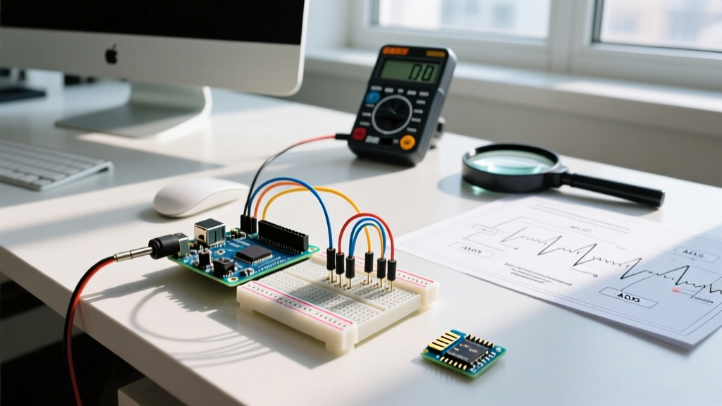
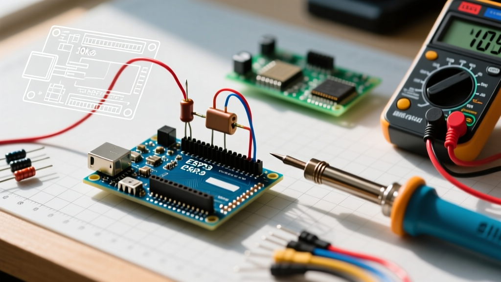
For this tutorial, we will build a monitor for a 12V sealed lead-acid (SLA) battery, which can reach up to 14.4V when charging. We will use the 22 kΩ / 10 kΩ pair.
- Connect R1: Solder or wire one leg of the 22 kΩ resistor to the positive terminal of your battery (or the voltage source you are measuring).
- Connect R2: Connect the other leg of R1 to one leg of the 10 kΩ resistor. This junction is your $V_{out}$.
- Ground the Circuit: Connect the remaining leg of R2 to the common ground of your battery AND the GND pin on your Arduino. Warning: A common ground is mandatory. Without it, the ADC has no reference point, and you will read floating noise.
- Wire to ADC: Connect the $V_{out}$ junction to the Arduino's A0 pin.
- Add a Filter Capacitor (Optional but Recommended): Place a 100 nF (0.1 µF) ceramic capacitor in parallel with R2 (between A0 and GND). This creates a low-pass filter that eliminates high-frequency electrical noise, drastically stabilizing your ADC readings.
The Arduino Sketch: ADC Conversion and Scaling
The Arduino Uno R3 features a 10-bit ADC, meaning it maps the 0-5V range to integer values between 0 and 1023. (Note: If you are using a newer Arduino Uno R4 Minima, it features a 12-bit ADC mapping to 0-4095, and you must adjust the divisor in the code accordingly).
const int analogPin = A0;
const float vRef = 5.0; // See calibration note below
const float r1 = 22000.0;
const float r2 = 10000.0;

void setup() {
  Serial.begin(9600);
  // Optional: Use internal 1.1V reference for high precision on low voltages
  // analogReference(INTERNAL);
}

void loop() {
  // Read the raw ADC value (0-1023 for 10-bit ADC)
  int adcRaw = analogRead(analogPin);

  // Convert raw ADC value to voltage at the A0 pin
  float vOut = adcRaw * (vRef / 1023.0);

  // Calculate the actual input voltage using the divider ratio
  float vIn = vOut * ((r1 + r2) / r2);

  Serial.print("Raw ADC: ");
  Serial.print(adcRaw);
  Serial.print(" | Calculated Voltage: ");
  Serial.print(vIn, 2);
  Serial.println(" V");

  delay(500);
}
Advanced Calibration: Solving the Vref Drift Problem
The most common reason makers abandon voltage dividers is inaccurate readings. If your multimeter reads 12.6V but your Arduino Serial Monitor reads 11.9V, your code isn't necessarily wrong—your hardware reference is lying to you.
The USB Vbus Drop
When you power an Arduino Uno R3 via the USB port, the 5V rail is not exactly 5.00V. The USB polyfuse and the onboard Schottky protection diode introduce a voltage drop. It is incredibly common to see the 5V pin sitting at 4.75V to 4.85V. If your sketch hardcodes vRef = 5.0, your final voltage calculation will be skewed by 3% to 5%.
The Fix: Take a high-quality digital multimeter, measure the voltage between the Arduino's 5V pin and GND pin while it is plugged in, and update the vRef constant in your code to that exact number (e.g., 4.82).
Using the Internal 1.1V Bandgap Reference
For mission-critical applications where Vcc might fluctuate (like a battery-powered Arduino running through a linear regulator), you can use the ATmega328P's internal 1.1V bandgap reference. By calling analogReference(INTERNAL) in your setup, the ADC maps 0-1023 to 0-1.1V. This requires you to change your voltage divider resistors to step your max voltage down to 1.0V instead of 5.0V, but it provides a highly stable, temperature-independent reference that ignores Vcc droop. You can read more about reference configurations in the official Arduino analogReference documentation.
Troubleshooting Common ADC Failure Modes
| Symptom | Root Cause | Solution |
|---|---|---|
| Readings fluctuate wildly (e.g., 12.1V to 12.8V) | High source impedance or EMI noise. | Add a 100nF capacitor across R2. Ensure R1+R2 is not >100kΩ. |
| Reading is stuck at 1023 (or 5.0V+) | $V_{in}$ exceeds the divider's design limits, or R2 is disconnected. | Verify R2 ground connection. Recalculate divider for higher max $V_{in}$. |
| Reading is consistently 4% low | USB Vbus voltage drop on the 5V reference rail. | Measure actual 5V pin voltage with a DMM and update vRef in code. |
| Arduino resets randomly when connecting $V_{in}$ | Ground loop or missing common ground causing current to backfeed through A0 clamping diodes. | Ensure battery GND and Arduino GND are tied together securely. |
When to Ditch the Divider: I2C Current/Voltage Sensors
While learning how to measure voltage with Arduino using a passive divider is a fundamental rite of passage, it has limitations. Resistors drift with temperature, they consume continuous current (wasting battery life in low-power IoT nodes), and they cannot measure current.
If your project requires high precision, bidirectional current sensing, or operates in a noisy industrial environment, upgrade to a dedicated I2C ADC like the Texas Instruments INA219 or INA226. Breakout boards for the INA219 (such as the Adafruit INA219 High Side DC Current Sensor, typically priced around $9.95) feature a 12-bit ADC, a programmable gain amplifier, and a shunt resistor all integrated into a single package. They communicate via I2C, completely bypassing the Arduino's internal ADC and its associated Vref drift issues, providing milliamp and millivolt accuracy right out of the box.