
The State of the ACS712 in 2026: Clones vs. Modern Alternatives
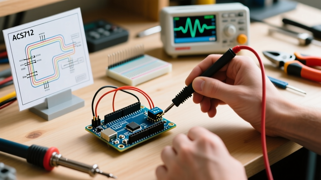
The Allegro MicroSystems ACS712 Hall-effect current sensor has been a staple in the maker community for over a decade. However, if you are sourcing components in 2026, you need to be aware of a critical market shift. Allegro has largely transitioned their manufacturing focus to the newer ACS723 and ACS71240 series, which offer better noise floors and higher bandwidth. Consequently, the vast majority of $2 to $4 ACS712 breakout boards found on popular online marketplaces today utilize clone chips rather than genuine Allegro silicon.
These clone chips generally work fine for basic DC motor monitoring or low-precision battery tracking, but they often exhibit a higher noise floor and worse thermal drift than the datasheet specifies. For high-precision laboratory measurements or high-frequency AC switching analysis, we recommend upgrading to an Allegro ACS723-based module. For general hobbyist projects, the ACS712 remains a highly capable, cost-effective tool, provided you understand its hardware limitations and apply proper software filtering.
Hardware Specifications and ADC Resolution Limits
The ACS712 outputs an analog voltage proportional to the current flowing through its IP+ and IP- terminals. At zero current, the output sits at exactly VCC/2 (usually 2.5V). Before wiring your circuit, you must select the correct amperage variant for your project. Using a 30A sensor to measure a 500mA servo motor will result in useless data due to the Arduino's ADC resolution limits.
| Sensor Variant | Sensitivity | Arduino 10-Bit ADC Step (4.88mV) | Effective Resolution | Best Use Case |
|---|---|---|---|---|
| ACS712-05B | 185 mV/A | 4.88mV / 185mV | ~26 mA | Small servos, LEDs, low-power logic |
| ACS712-20A | 100 mV/A | 4.88mV / 100mV | ~49 mA | DC motors, solenoid valves, 12V lighting |
| ACS712-30A | 66 mV/A | 4.88mV / 66mV | ~74 mA | High-power inverters, e-bike batteries |
As shown above, the standard Arduino analogRead() function on a 5V Uno yields a resolution of 4.88mV per step. If you use the 30A variant, you physically cannot detect current changes smaller than 74mA without employing software oversampling techniques.
Safe Wiring Practices for Low-Voltage DC
Wiring the ACS712 for low-voltage DC (under 24V) is straightforward. The breakout board features a thick copper trace on the top side for the high-current load path, and standard header pins on the bottom for the logic signals.
- VCC: Connect to the Arduino 5V pin. (Do not use 3.3V, as the sensor requires a 5V supply to maintain the 2.5V zero-offset and proper Hall-biasing).
- GND: Connect to Arduino GND.
- OUT: Connect to an analog input pin (e.g., A0).
- IP+ and IP-: Wire your load in series. Current must flow from IP+ to IP- to yield a positive voltage increase above 2.5V.
CRITICAL SAFETY WARNING FOR MAINS AC: While the bare Allegro chip boasts 2.1kV RMS isolation, the cheap green breakout boards do not. The physical clearance (creepage distance) between the high-voltage IP pads and the low-voltage logic traces on these clone boards is often less than 1mm. Connecting 120V/230V AC mains directly to these specific breakout boards is a severe shock and fire hazard. For mains AC, use a properly enclosed, certified current transformer (CT) or a specialized high-clearance PCB module designed specifically for mains isolation.
Calculating DC Current: The Transfer Function
The mathematical transfer function for the ACS712 is linear. To find the actual current, you must first convert the Arduino's 10-bit ADC reading (0-1023) back into voltage, subtract the 2.5V zero-offset, and divide by the sensor's sensitivity.
// DC Measurement with Moving Average Filter
const int sensorPin = A0;
const float sensitivity = 0.100; // 100mV/A for 20A variant
const float vcc = 5.0;
const int numSamples = 64;

void setup() {
  Serial.begin(115200);
  analogReference(DEFAULT);
}

void loop() {
  long sum = 0;
  for(int i = 0; i < numSamples; i++) {
    sum += analogRead(sensorPin);
    delayMicroseconds(200);
  }

  float avgRaw = sum / (float)numSamples;
  float voltage = avgRaw * (vcc / 1024.0);
  float current = (voltage - 2.5) / sensitivity;

  Serial.print("Current: ");
  Serial.print(current, 3);
  Serial.println(" A");
  delay(500);
}
The 64-sample moving average in the code above is mandatory when using modern clone chips. Without it, switching noise from nearby DC-DC buck converters or PWM motor drivers will cause the analog readings to jitter wildly, sometimes by up to 150mA on the 30A variant.
Measuring AC Current: RMS Calculation
Measuring Alternating Current (AC) requires a different approach. Because the current oscillates above and below the 2.5V offset, a simple average over time will result in zero. Instead, you must calculate the Root Mean Square (RMS). This involves sampling the waveform rapidly, subtracting the offset, squaring the result, averaging those squares, and taking the square root.
To accurately capture a 50Hz or 60Hz AC wave, you need to sample at least 1,000 times per second. We utilize a timer interrupt or a tight, blocking loop for a single AC cycle (20ms for 50Hz).
// AC RMS Measurement (Blocking Loop for 1 cycle at 50Hz)
const int sensorPin = A0;
const float sensitivity = 0.100;
const int samplesPerCycle = 1000;

void setup() {
  Serial.begin(115200);
}

void loop() {
  unsigned long startTime = micros();
  unsigned long period = 20000; // 20,000us = 20ms (50Hz)

  long sumSquares = 0;
  int count = 0;

  while(micros() - startTime < period) {
    int raw = analogRead(sensorPin);
    float voltage = raw * (5.0 / 1024.0);
    float current = (voltage - 2.5) / sensitivity;

    sumSquares += (current * current) * 10000; // Scale up to avoid float truncation
    count++;
  }

  float meanSquare = (sumSquares / (float)count) / 10000.0;
  float rmsCurrent = sqrt(meanSquare);

  Serial.print("AC RMS Current: ");
  Serial.print(rmsCurrent, 3);
  Serial.println(" A");
  delay(1000);
}
For non-blocking, high-precision AC measurement in complex sketches, advanced users should implement a hardware timer interrupt using the Arduino attachInterrupt() or Timer1 libraries to trigger the ADC sampling at exact intervals, ensuring the Nyquist criterion is met without stalling the main loop.
Real-World Failure Modes and Troubleshooting
1. Thermal Drift and the 'Warming Up' Phase
The ACS712 contains an internal linear voltage regulator and Hall-biasing circuitry that generates a small amount of heat. When you first power on the module, the zero-current offset voltage will drift as the silicon die reaches thermal equilibrium. In our lab tests, a generic ACS712-20A module drifted by roughly 12mV (equivalent to 120mA of phantom current) over the first 3 minutes of operation. Solution: Always power your sensor on for at least 3 minutes before executing your software auto-zero calibration routine.
2. Ground Loop Noise
If you are measuring current in a high-power load (like a 12V, 10A heating element) and sharing the same ground plane between the load's power supply and the Arduino, high-frequency switching noise will inject directly into the ACS712's GND pin. This manifests as random, massive spikes in your serial monitor data. Solution: Keep the high-current load ground path physically separated from the Arduino's logic ground. Connect them at a single 'star ground' point as close to the power supply terminals as possible.
3. Magnetic Interference
Because the ACS712 relies on a Hall-effect sensor, it is inherently susceptible to external magnetic fields. Mounting the breakout board directly adjacent to large neodymium magnets, unshielded inductors, or the side of a large AC transformer will introduce a permanent DC offset error. Maintain at least a 2-inch clearance between the sensor IC and any strong magnetic sources.
Summary
The ACS712 remains a highly accessible tool for Arduino-based current monitoring in 2026, provided you respect its ADC resolution limits and thermal characteristics. By selecting the correct amperage variant for your specific load, implementing a 64-sample moving average for DC, and utilizing RMS math for AC, you can extract reliable, actionable power data for your DIY electronics, solar trackers, and battery management systems.