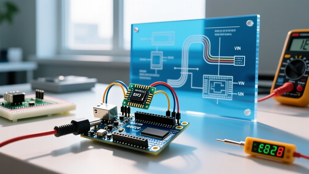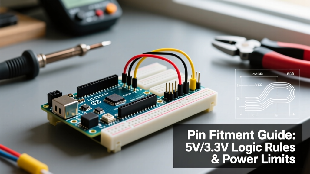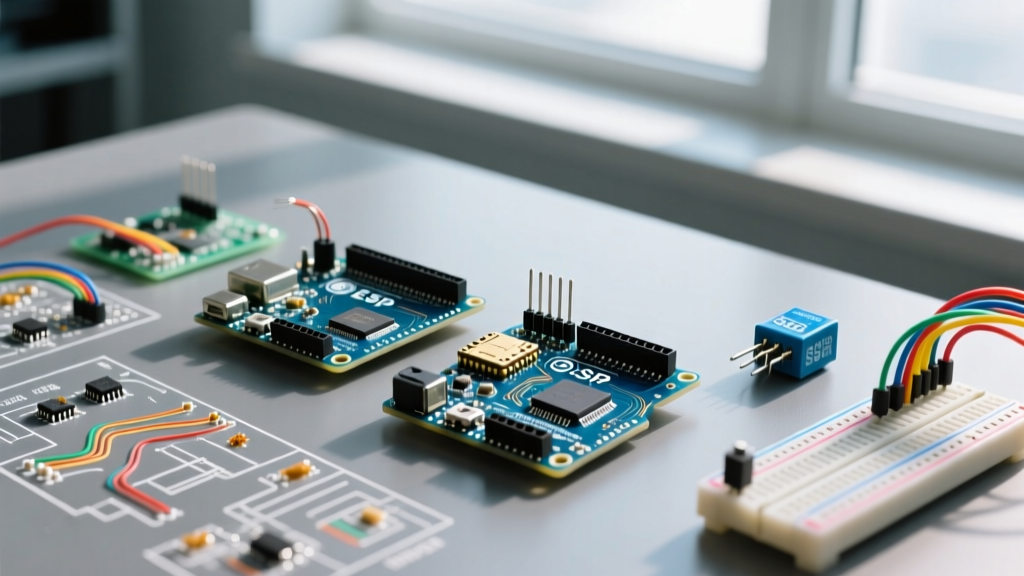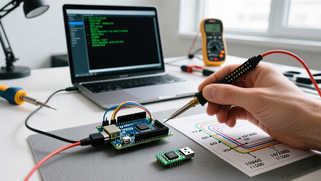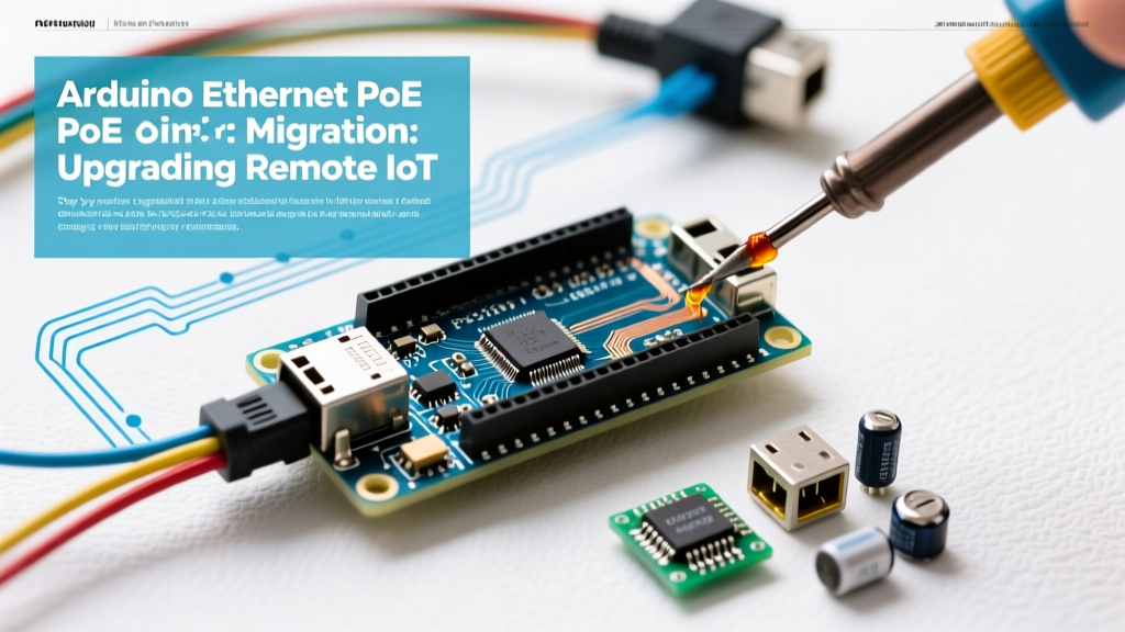

Deploying remote IoT sensors in industrial or agricultural environments often exposes the limitations of standard Wi-Fi and dual-cable (power plus data) setups. Wi-Fi suffers from latency, packet loss, and range issues in electrically noisy or physically dense environments. Running separate CAT6 and AC power lines to every node drastically increases installation costs. Migrating to an Arduino Ethernet PoE (Power over Ethernet) architecture solves both problems by delivering data and power over a single copper cable. However, transitioning from standard barrel-jack powered boards or SPI-based Wi-Fi modules to a robust PoE infrastructure requires careful hardware selection, power budgeting, and protocol compliance.
The Migration Baseline: Why Upgrade to PoE?
Before ripping out your existing ENC28J60 modules or ESP8266 Wi-Fi nodes, it is critical to quantify the operational gains of PoE. The primary advantage is the elimination of local power supplies, which are the number one point of failure in remote deployments due to capacitor degradation and thermal stress.
| Architecture | Max Data Rate | Cable Run Limit | Reliability (Industrial) | Est. Node Cost (2026) |
|---|---|---|---|---|
| Wi-Fi (ESP8266/ESP32) | 72 Mbps (802.11n) | ~50m (indoor) | Low (Interference prone) | $8 - $14 |
| Standard Ethernet + DC Jack | 10/100 Mbps | 100m (CAT5e/6) | Medium (Requires local PSU) | $25 - $35 |
| Active PoE (802.3af) | 10/100 Mbps | 100m (CAT5e/6) | High (Centralized UPS) | $32 - $45 |
Hardware Selection: SPI Shields vs. RMII PHY Boards
When planning your Arduino Ethernet PoE migration, you must choose between adding a PoE shield to a classic Arduino (like the Uno or Mega) or migrating to a microcontroller with native Ethernet MAC support. In 2026, the landscape is dominated by two chipsets: the W5500 and the LAN8720A.
Option A: W5500 PoE Shields (The Classic Path)
The W5500 chip remains the gold standard for SPI-based Ethernet on 8-bit and 32-bit Arduinos. It features a fully offloaded TCP/IP stack, meaning the MCU does not waste RAM processing network packets. When selecting a W5500 PoE shield, you must verify the presence of an integrated DC-DC buck converter (typically stepping 48V down to 5V). According to the official Arduino Ethernet library documentation, the W5500 supports up to 8 simultaneous sockets, which is ideal for MQTT and HTTP polling. Expect to pay between $18 and $24 for a quality W5500 PoE shield from reputable manufacturers like Seeed Studio or DFRobot.
Option B: ESP32 with RMII PHY (The Modern Upgrade)
Many makers are migrating away from 8-bit Arduinos entirely for networked tasks, opting instead for ESP32 boards with native RMII (Reduced Media Independent Interface) Ethernet PHYs, such as the LAN8720A. Boards like the Olimex ESP32-PoE integrate the PoE PD (Powered Device) controller, the Ethernet PHY, and the ESP32 onto a single PCB. This eliminates the SPI bottleneck, allowing for true 100Mbps throughput and TLS-encrypted MQTT without dropping packets. These boards typically cost $22 to $28 and represent the most cost-effective, high-performance migration path for new deployments.
Power Budgeting and the Passive vs. Active PoE Trap
The most catastrophic failure mode during an Arduino Ethernet PoE migration is confusing Passive PoE with Active PoE. This mistake routinely destroys microcontrollers and PC motherboards.
Critical Warning: Never plug a Passive 24V or 48V PoE injector directly into an Arduino shield that lacks an isolated DC-DC step-down module. Passive injectors force voltage onto the Ethernet cable's spare pairs continuously, without checking if the receiving device supports it.
Understanding IEEE 802.3af Compliance
True Active PoE follows the IEEE 802.3af standard. An active PoE switch or injector performs a 'handshake' by sending a low-voltage probe to detect a 25kΩ signature resistor on the Powered Device (PD). Only when this resistor is detected does the switch apply the full 48V. If your Arduino shield does not have a dedicated PD controller chip (such as the TI TPS23753A or Silvertel V1410), an active switch will simply refuse to output power, leaving your node dead.
- Class 0 Devices: Default classification, requesting up to 12.95W. Overkill for a standard Arduino drawing 50mA, but standard for most off-the-shelf PoE shields.
- Class 1 Devices: Requests up to 3.84W. Ideal for low-power sensor nodes, allowing a 4-port PoE switch to power more devices simultaneously.
- Power Loss over Distance: While CAT6 can carry data 100 meters, voltage drop on the 48V line can be significant if using thin 24AWG CCA (Copper Clad Aluminum) cables. Always use 23AWG solid copper CAT6 for runs exceeding 40 meters to ensure the shield's buck converter receives at least 36V at the input.
Step-by-Step Pinout and Wiring Migration
When migrating from an ENC28J60 (which requires heavy MCU RAM usage) to a W5500 PoE shield, the physical wiring and SPI pin mapping must be updated. The ENC28J60 often uses custom SPI pins on non-Uno boards, whereas the W5500 strictly adheres to the ICSP header.
- SPI Routing: Connect MOSI, MISO, and SCK to the 6-pin ICSP header on the center of the Arduino Uno/Mega. Do not use digital pins 11, 12, and 13 if you are using an Arduino Mega, as the Mega's SPI bus is routed exclusively to the ICSP header.
- Chip Select (CS): The W5500 requires a dedicated CS pin. On an Uno, use Pin 10. On a Mega, use Pin 53. Ensure this pin is set to
OUTPUTin yoursetup()function, even if you use a different pin for the actual Ethernet library CS parameter, to prevent the hardware SPI controller from entering slave mode. - Reset Pin: Tie the W5500 hardware reset pin to the Arduino's reset line via a 100nF capacitor and a 10kΩ pull-up resistor to ensure the Ethernet chip re-initializes cleanly when the MCU is flashed or power-cycled.
Troubleshooting Common Migration Failures
Even with the correct hardware, environmental and architectural edge cases can cause intermittent failures. Use this diagnostic checklist when your newly migrated PoE nodes fail to connect.
1. The 'Phantom Power' Ground Loop
If your Arduino is connected to a PC via USB for debugging while simultaneously receiving 48V PoE, you risk creating a ground loop. The PoE shield's DC-DC converter grounds the 5V output to the Ethernet cable's shield/ground, which may be at a different potential than your PC's earth ground. Solution: Use a USB isolator (ADuM4160 based) during debugging, or physically cut the 5V trace on the shield's USB header to prevent back-feeding power into your PC's motherboard.
2. IP Address Collisions on Static Networks
When scaling from 2 nodes to 50 nodes, hardcoding IP addresses in the Arduino sketch becomes unmanageable and leads to ARP conflicts. Solution: Migrate your sketch to use DHCP. The W5500's hardware TCP/IP stack handles DHCP discovery natively. If your industrial network disables DHCP for security, implement a MAC-address-based IP assignment table on your router, and program the Arduino's MAC address (usually printed on a sticker on the shield) into your DHCP server's reservation list.
3. Switch Port Power Budget Exhaustion
A standard 8-port 802.3af PoE switch might have a total power budget of 60W. If you connect eight Arduino nodes equipped with relays, heaters, or high-draw cellular fallback modules that pull 10W each, the switch will trigger its over-current protection and shut down random ports. Solution: Audit the peak current draw of your sensors and actuators. Use a multimeter to measure the 5V rail current during actuator engagement, and ensure the total wattage of all connected nodes stays below 80% of the switch's rated PoE budget.
Summary
Migrating to an Arduino Ethernet PoE architecture transforms fragile, short-range prototypes into enterprise-grade IoT deployments. By selecting the correct W5500 or RMII-based hardware, strictly adhering to active 802.3af power standards, and isolating debug connections, you ensure your remote nodes remain online through power outages and environmental stress. Plan your cable runs with solid copper CAT6, respect the SPI pinouts, and let the Ethernet handle the heavy lifting.