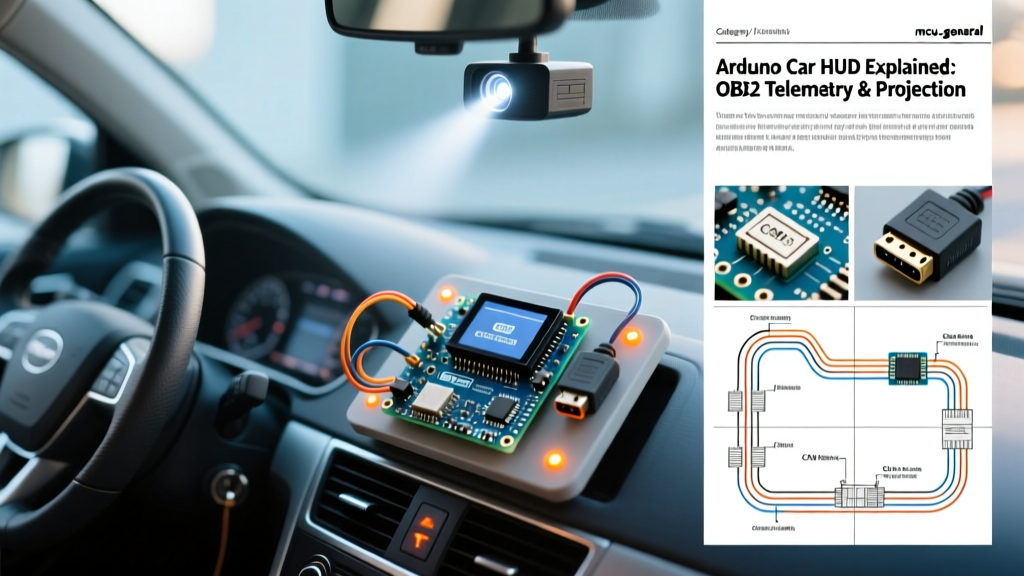

The Anatomy of an Arduino Car HUD
A Head-Up Display (HUD) projects critical telemetry directly into the driver's line of sight, eliminating the need to look down at the dashboard. While commercial units often cost upwards of $200 and lock you into proprietary apps, building an Arduino car HUD offers complete control over data parsing, UI rendering, and optical alignment. As of 2026, the maker ecosystem provides high-speed CAN bus transceivers and ultra-bright IPS TFT displays that make DIY HUDs brighter, faster, and more reliable than ever before.
This concept explainer breaks down the three core pillars of a DIY automotive HUD: telemetry acquisition, microcontroller processing, and combiner optics.
Pillar 1: Telemetry Acquisition (OBD-II vs. Direct CAN)
To display speed, RPM, and coolant temperature, your microcontroller must talk to the vehicle's ECU. There are two primary methods for achieving this in an Arduino car HUD project.
Method A: The ELM327 Bluetooth Bridge
The most common entry point is using an ELM327 v1.5 OBD-II Bluetooth adapter paired with an HC-05 Bluetooth module. The MCU sends ASCII AT commands to request specific Parameter IDs (PIDs). For example, requesting PID 0x0C returns Engine RPM, while 0x0D returns Vehicle Speed. You can explore the full list of standard SAE J1979 PIDs in the OBD-II PIDs reference.
Limitation: Bluetooth polling introduces latency. You will typically max out at 10-15 Hz update rates, which causes analog gauge needles on the HUD to stutter at high speeds.
Method B: Direct CAN Bus Sniffing (The 2026 Standard)
For a fluid, 60 FPS UI, modern builders bypass the ELM327 entirely and wire directly into the OBD-II port's CAN High and CAN Low pins (Pins 6 and 14). Using an MCP2515 CAN controller paired with a TJA1050 transceiver (total cost: ~$4), the Arduino passively sniffs the vehicle's CAN bus frames. This allows you to decode manufacturer-specific broadcast messages (like instantaneous fuel consumption or steering angle) at 100+ Hz. For a deep dive into CAN frame decoding, the CSS Electronics OBD2 guide is an invaluable resource.
Pillar 2: Microcontroller Selection & Processing
Rendering a UI while simultaneously decoding hex CAN frames requires significant overhead. The classic Arduino Uno (ATmega328P) is no longer sufficient for modern HUDs due to its 16MHz clock and 2KB SRAM. Below is a comparison of the top MCUs for this application.
| Microcontroller | Price (2026) | Clock Speed / Cores | CAN Bus Support | Verdict for HUD |
|---|---|---|---|---|
| Arduino Nano 33 IoT | $11.00 | 48MHz / Single Core | Requires external MCP2515 | Good for simple text-only displays. |
| ESP32-S3 DevKit | $6.50 | 240MHz / Dual Core | Native TWAI (CAN) controller | Best Overall. Pin one core to CAN decoding, the other to TFT rendering. |
| Teensy 4.1 | $38.00 | 600MHz / Single Core | Native CAN (FlexCAN) | Overkill for 2D, but ideal if rendering 3D OpenGL models via external GPU. |
Software Architecture Note: When using the ESP32-S3, never use delay() in your main loop. Utilizing FreeRTOS, assign the CAN read function to Core 0 and the display rendering (via the Adafruit GFX library) to Core 1. This ensures that a heavy UI redraw never blocks incoming telemetry data.
Pillar 3: Combiner Optics and Projection Physics
The most misunderstood aspect of an Arduino car HUD is the optics. You cannot simply place a TFT screen on the dashboard and reflect it off the windshield. Doing so results in two major failures: ghosting (double reflections) and severe eye strain.
The Focal Distance Problem
Human eyes focus on the road at optical infinity (roughly 2 to 3 meters ahead). If your HUD display is physically located 30cm from your eyes, your ciliary muscles must rapidly refocus between the road and the HUD, causing fatigue within minutes.
The Optical Rule of Thumb: A proper automotive HUD must use a convex mirror or a specialized lens array to project a 'virtual image' that appears to float at least 1.5 to 2.0 meters in front of the driver, matching the focal plane of the road ahead.
The Combiner Glass
Instead of reflecting off the car's windshield (which causes ghosting due to the laminated glass layers), high-end DIY builds use a dedicated 'combiner glass' mounted on the dash. This is a piece of optical acrylic coated with a dielectric beam splitter film. The ideal ratio for a car interior is 70% Transmittance / 30% Reflectance. This allows the driver to see through the glass clearly while reflecting the high-contrast TFT display beneath it.
Display Selection
To combat direct sunlight, your source display must output at least 800 nits of brightness. Standard 2.8-inch ILI9341 TFTs (~300 nits) will wash out entirely at noon. As of 2026, builders are utilizing 3.5-inch IPS OCA-bonded displays or Nextion HMI panels with software-controlled backlight drivers that push 1000+ nits. Crucially, the UI must be rendered in high-contrast colors (cyan and bright green on pure black #000000 backgrounds) to maximize the beam splitter's reflective efficiency.
Real-World Failure Modes & Edge Cases
When moving an Arduino project from the workbench to a vehicle environment, you will encounter specific automotive edge cases:
- CAN Bus Sleep Mode: Modern vehicles put the CAN bus to sleep 10 minutes after ignition off. If your HUD is wired to constant 12V and keeps the MCP2515 active, it will drain the car battery. You must implement an ignition-switched power relay or use a CAN wake-up interrupt.
- Thermal Throttling: Dashboard temperatures in summer can exceed 75°C (167°F). Standard LCD liquid crystals will turn black and bleed at these temperatures. You must use automotive-rated IPS panels or implement a thermal shutdown routine using an onboard thermistor to cut the backlight when ambient temps exceed 65°C.
- Voltage Transients: A car's 12V system can experience load dump spikes up to 40V during cranking. Never power an ESP32 directly from a cheap cigarette lighter buck converter. Use an automotive-grade DC-DC buck converter (like the LM2596HV with added TVS diode protection) to ensure a clean 5V/3.3V rail.
Summary
Building a functional Arduino car HUD is a masterclass in multidisciplinary engineering. It requires mastering CAN bus arbitration for real-time telemetry, leveraging dual-core FreeRTOS architectures for stutter-free rendering, and applying optical physics to project a virtual image safely into the driver's focal plane. By selecting the right beam splitter optics and an ESP32-S3 backbone, you can create a heads-up display that rivals—and often exceeds—factory-installed automotive telemetry systems.