
In the evolving landscape of DIY robotics and microcontroller projects in 2026, the bulky and inefficient L298N motor driver has largely been relegated to the spare parts bin. Modern makers demand higher efficiency, lower voltage drop, and compact footprints. Enter the DRV8833, a dual H-bridge motor driver IC from Texas Instruments that perfectly bridges the gap between low-cost toy motors and high-performance robotic actuators. This comprehensive DRV8833 Arduino tutorial will walk you through exact wiring schematics, advanced PWM code implementation, and critical hardware edge cases that most basic guides overlook.
Why Choose the DRV8833 for Arduino Projects?
The DRV8833 is designed to drive two DC brushed motors or a single bipolar stepper motor. Unlike older BJT-based drivers that waste significant power as heat (often dropping 2V to 3V across the transistors), the DRV8833 utilizes NMOS and PMOS MOSFETs. This results in a remarkably low on-resistance (RDS(on)) of roughly 0.35Ω per FET, meaning your motors actually receive the voltage you intend to send them.
Operating from a motor supply voltage (VM) of 2.7V to 10.8V, it is perfectly suited for 2S LiPo batteries (7.4V nominal) or standard 6V AA battery packs. Each channel can deliver 1.5A of continuous current and handle 2A peak currents, making it ideal for micro-sumo robots, autonomous line followers, and motorized camera sliders.
DRV8833 vs. L298N vs. TB6612FNG
Understanding where the DRV8833 sits in the 2026 motor driver ecosystem helps justify its selection. Below is a technical comparison of the most common dual H-bridge breakout boards available on the market.
| Feature | DRV8833 | TB6612FNG | L298N |
|---|---|---|---|
| Max Continuous Current | 1.5A per channel | 1.2A per channel | 2.0A per channel |
| Motor Voltage (VM) | 2.7V – 10.8V | 2.5V – 13.5V | 5V – 35V |
| Voltage Drop | ~0.4V (MOSFET) | ~0.5V (MOSFET) | ~2.0V - 3.0V (BJT) |
| Logic Voltage (VCC) | 2.7V – 5.5V | 2.7V – 5.5V | 5V (Internal Reg) |
| Typical Price (2026) | $3.50 – $5.00 | $6.00 – $9.00 | $4.00 – $7.00 |
| Sleep Mode | Yes (nSLEEP pin) | Yes (STBY pin) | No |
Source: Component specifications derived from the Texas Instruments DRV8833 product page and manufacturer datasheets.
Pinout and Critical Wiring Rules
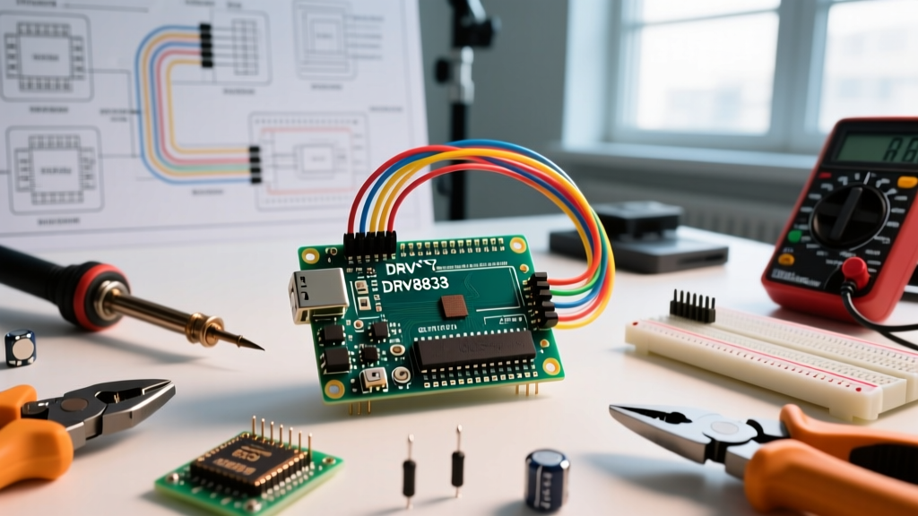
Wiring the DRV8833 to an Arduino Uno R3, Nano, or the newer Arduino Uno R4 Minima requires attention to both the motor power domain (VM) and the logic domain (VCC). A common mistake is tying VCC directly to a high-voltage battery, which will instantly destroy the logic gates.
Power Domain Connections
- VM (Motor Supply): Connect to your battery positive (e.g., 7.4V LiPo). Must include a decoupling capacitor (10µF to 47µF) placed as close to the pin as possible to handle inductive voltage spikes.
- VCC (Logic Supply): Connect to the Arduino 5V or 3.3V pin. This powers the internal logic level shifters. Do not exceed 5.5V.
- GND: Connect the DRV8833 GND to the Arduino GND and the battery GND. A common ground is mandatory for signal reference.
Control and Fault Pins
- AIN1, AIN2, BIN1, BIN2: Connect to Arduino digital PWM pins (e.g., D5, D6, D9, D10) for speed and direction control.
- nSLEEP: Active low sleep pin. Crucial: If your breakout board does not have an onboard pull-up resistor, you must tie this to VCC. If left floating, internal leakage can pull the pin low, putting the IC into a high-impedance sleep state.
- nFAULT: Open-drain fault indicator. Goes LOW when Overcurrent Protection (OCP) or Thermal Shutdown (TSD) triggers. Requires an external 10kΩ pull-up resistor to VCC to read correctly via
digitalRead().
Advanced Arduino Code Implementation
Basic tutorials rely on blocking delay() functions, which is unacceptable for modern robotics requiring sensor fusion or PID control loops. Below is a robust, non-blocking C++ implementation using a custom class structure. This code utilizes the Arduino analogWrite() function for PWM speed control while managing the decay modes inherently.
// DRV8833 Motor Control Class for Arduino
// Optimized for non-blocking robotic applications

class DRV8833Motor {
  private:
    uint8_t pinIN1;
    uint8_t pinIN2;
    uint8_t pwmChannel;

  public:
    DRV8833Motor(uint8_t in1, uint8_t in2) {
      pinIN1 = in1;
      pinIN2 = in2;
      pinMode(pinIN1, OUTPUT);
      pinMode(pinIN2, OUTPUT);
    }

    // Speed range: -255 (Reverse) to 255 (Forward)
    void setSpeed(int speed) {
      if (speed > 0) {
        analogWrite(pinIN1, speed);
        analogWrite(pinIN2, 0);
      } else if (speed < 0) {
        analogWrite(pinIN1, 0);
        analogWrite(pinIN2, -speed);
      } else {
        // Fast Decay / Braking (Both pins LOW)
        analogWrite(pinIN1, 0);
        analogWrite(pinIN2, 0);
      }
    }

    // Coast mode (High impedance, motor spins freely)
    void coast() {
      digitalWrite(pinIN1, HIGH);
      digitalWrite(pinIN2, HIGH);
    }
};

// Initialize Motor A on pins 5 and 6
DRV8833Motor motorA(5, 6);

void setup() {
  Serial.begin(115200);
  Serial.println("DRV8833 Advanced Control Initialized");

  // Ensure nSLEEP is HIGH if tied to a digital pin
  // pinMode(8, OUTPUT); digitalWrite(8, HIGH);
}

void loop() {
  // Accelerate forward
  for(int i = 0; i <= 255; i += 5) {
    motorA.setSpeed(i);
    delay(20);
  }

  // Coast for 1 second
  motorA.coast();
  delay(1000);

  // Hard brake and reverse
  motorA.setSpeed(0);
  delay(500);
  motorA.setSpeed(-200);
  delay(2000);

  // Stop completely
  motorA.setSpeed(0);
  delay(2000);
}
Troubleshooting Common DRV8833 Failures
Even with correct wiring, makers frequently encounter edge cases when integrating the DRV8833 into complex circuits. Here is how to diagnose and resolve the most common hardware and software anomalies.
1. Motor Whining or High-Pitched Squeal
The Cause: The default PWM frequency on Arduino Uno pins 5 and 6 is approximately 980 Hz, while pins 9 and 10 run at 490 Hz. Frequencies under 20 kHz fall within the human hearing range, causing the motor coils and ceramic capacitors to vibrate audibly.
The Fix: Alter the hardware timer prescalers to push the PWM frequency above 20 kHz. For pins 5 and 6 (Timer 0), changing the prescaler will affect millis() and delay(). Instead, use pins 9 and 10 (Timer 1) and adjust the TCCR1B register to achieve a 31.25 kHz PWM frequency, rendering the motor operation silent.
2. Erratic Motor Stalling and Random Direction Changes
The Cause: Voltage sag on the VM line. When a motor starts, it draws a massive stall current (often 3x to 5x the continuous rating). If your battery cannot supply this transient current, the VM voltage dips below the DRV8833's Undervoltage Lockout (UVLO) threshold of 2.7V. The IC resets, causing erratic behavior.
The Fix: Add a large bulk electrolytic capacitor (470µF or higher) directly across the VM and GND terminals on your breadboard or custom PCB. Additionally, ensure your battery's C-rating is sufficient for the peak load.
3. Overcurrent Protection (OCP) False Triggers
The Cause: The DRV8833 features internal OCP set at roughly 1.5A to 2.0A. However, the OCP circuit includes a blanking time (typically 1µs). If you are driving highly inductive loads or using very long, unshielded motor wires, EMI can couple into the logic lines, causing the IC to falsely register a fault.
The Fix: Keep motor wires as short as possible. If using a custom PCB, route high-current motor traces away from sensitive logic traces. Consult advanced layout guidelines from Pololu's motor driver design resources for optimal ground plane isolation.
Understanding Decay Modes: Fast vs. Slow
The DRV8833 handles current decay differently depending on the state of the input pins. Understanding this is critical for precise speed control and stepper motor microstepping.
- Slow Decay (Braking): Achieved by setting one input HIGH and the other LOW, but utilizing PWM on the LOW side (or using the internal synchronous rectification). This provides smooth current flow and acts as a dynamic brake.
- Fast Decay (Coasting): Achieved by setting both inputs HIGH. The H-bridge disables the FETs, allowing the motor to spin freely. Current dissipates rapidly through the body diodes.
For most DC brushed motor applications in 2026, relying on the default slow-decay braking (setting the opposing pin to 0% PWM while the active pin receives the speed PWM) yields the most linear speed-to-voltage response.
Frequently Asked Questions
Can I use the DRV8833 with a 3.3V microcontroller like the ESP32?
Yes. The DRV8833 logic threshold is proportional to VCC. If you power the VCC pin with 3.3V from your ESP32, the logic HIGH threshold drops accordingly, making it perfectly compatible with 3.3V GPIO pins without the need for a logic level shifter.
Is the DRV8833 suitable for driving a stepper motor?
While it can drive a single bipolar stepper motor using the two H-bridges, it lacks the internal current regulation and step-sequencing logic found in dedicated stepper drivers like the A4988 or TMC2209. You would need to implement the current limiting and microstepping decay algorithms entirely in Arduino software, which is computationally heavy and generally not recommended for high-precision CNC or 3D printer applications.
Expert Tip: Always measure the actual current draw of your motors under stall conditions before finalizing your power supply. A motor rated for 500mA continuous can easily pull 2.5A at startup, triggering the DRV8833's thermal shutdown if the ambient temperature is high and the copper pours on your breakout board are insufficient for heat dissipation.