
The Case for Magnetic: Why Ditch Optical Encoders?
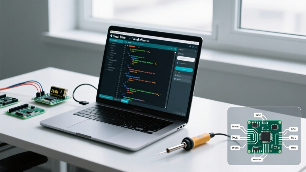
For years, the KY-040 rotary module and optical fork sensors have been the default for Arduino-based position tracking. However, as maker projects evolve into demanding CNC routers, robotic arms, and closed-loop stepper systems, optical encoders reveal critical failure modes. Optical sensors rely on an LED and phototransistor separated by a slotted disk. In dusty environments, particulate ingress causes missed pulses. Furthermore, mechanical shaft wobble exceeding just 0.1mm can cause the optical disk to scrape the sensor housing, resulting in catastrophic mechanical binding.
Migrating to a hall effect encoder Arduino setup eliminates these physical limitations. By reading the angular position of a magnet mounted on the shaft end, magnetic encoders offer absolute positioning, infinite mechanical life, and total immunity to dust and oil contamination. According to CUI Devices' engineering analysis on encoder technologies, magnetic absolute encoders drastically reduce system calibration time because they retain their position data even after power loss, unlike incremental optical alternatives.
Silicon Selection Matrix: AS5600 vs. AS5048A vs. TLE5012B
Choosing the right Hall IC depends on your required resolution, interface speed, and budget. Below is a 2026 market comparison of the most popular magnetic encoder ICs for microcontroller integration.
| IC Model | Resolution | Interface | Avg. Price (2026) | Best Use Case |
|---|---|---|---|---|
| AMS AS5600 | 12-bit (4096 steps) | I2C / Analog | $2.50 - $3.50 | Gimbal tracking, basic robotic joints, volume knobs |
| AMS AS5048A | 14-bit (16384 steps) | SPI | $12.00 - $16.00 | Closed-loop steppers, robotic arm joints, CNC dials |
| Infineon TLE5012B | 15-bit (32768 steps) | SSC (SPI-like) | $8.00 - $11.00 | High-precision BLDC motor commutation |
The #1 Migration Failure: Magnet Geometry and Air Gap
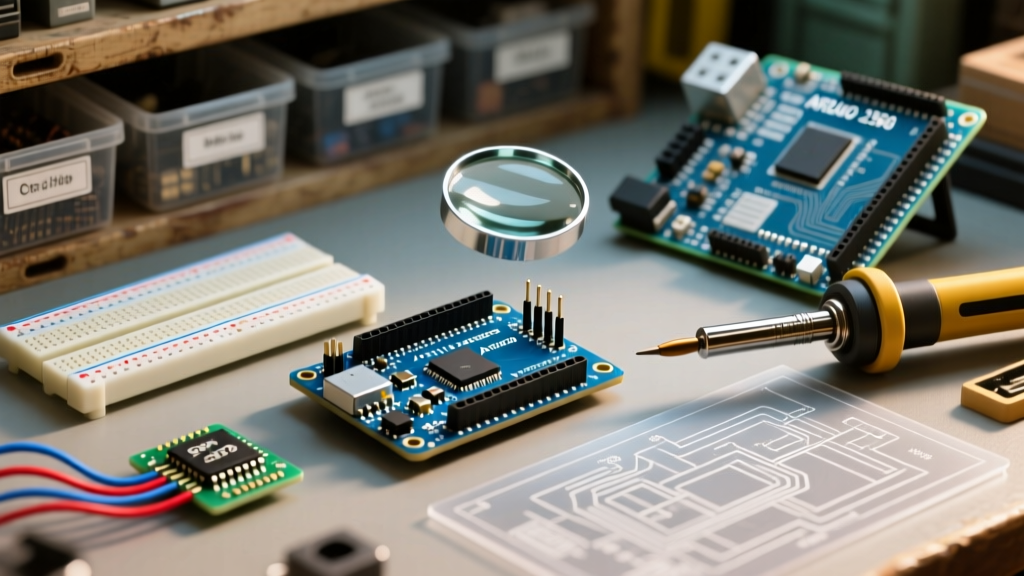
The most common reason a hall effect encoder Arduino migration fails is the use of the wrong magnet. Most off-the-shelf neodymium magnets are axially magnetized (North on the top flat face, South on the bottom). Hall ICs require a diametrically magnetized cylinder, where the N-S split runs across the diameter of the circular face.
Expert Tip: For the AS5600, purchase a 6mm diameter by 2.5mm thick N35 or N52 diametrically magnetized neodymium cylinder. Standard 6x3mm magnets often saturate the sensor's internal GMR/Hall array, causing non-linear output at the poles.
Strict Air Gap Tolerances
- AS5600: Requires a strict air gap of 1.5mm to 2.0mm between the magnet face and the IC package. Exceeding 2.5mm results in a weak magnetic field and increased jitter.
- AS5048A: More forgiving, operating optimally between 1.0mm and 3.0mm.
- TLE5012B: Optimal at 1.5mm, but features an integrated auto-calibration routine that compensates for slight gap variations over temperature.
Step-by-Step Migration: Upgrading to the AS5600 (I2C)
The AS5600 is the most accessible entry point for makers migrating from I2C potentiometers or basic rotary encoders. It operates at the default I2C address 0x36.
Wiring and Hardware Setup
- Connect VCC to the Arduino 5V or 3.3V pin (the AS5600 is tolerant of both, but 3.3V is preferred for cleaner analog out).
- Connect GND to Arduino GND.
- Connect SDA to A4 (Uno/Nano) or SDA (Mega/ESP32).
- Connect SCL to A5 (Uno/Nano) or SCL (Mega/ESP32).
- Critical: Tie the DIR pin to GND to set the clockwise direction mapping. Leaving it floating will cause erratic directional readings.
Software Implementation
While you can write raw I2C wire commands, the community-standard approach in 2026 is using Rob Tillaart's AS5600 Arduino Library. It handles the internal angle conversion and provides built-in filtering.
#include <Wire.h>
#include <AS5600.h>

AS5600 as5600(&Wire);

void setup() {
  Serial.begin(115200);
  Wire.begin();
  as5600.begin();
  as5600.setDirection(AS5600_CLOCK_WISE);
}

void loop() {
  Serial.println(as5600.readAngle() * AS5600_RAW_TO_RADIANS);
  delay(10);
}
Advanced Migration: High-Speed SPI with the AS5048A
For closed-loop stepper motors or robotic arms requiring sub-0.05 degree accuracy, the AS5600's 12-bit resolution and I2C bus latency (typically 1ms polling) are insufficient. The AS5048A provides 14-bit resolution over a high-speed SPI bus.
The 5V Logic Level Trap
The AS5048A MISO pin is 5V tolerant, meaning it can safely send data to a 5V Arduino Uno. However, the SCK, MOSI, and CS pins are strictly 3.3V. Driving them with 5V logic will permanently degrade the IC over time. If you are using a 5V Arduino, you must use a bidirectional logic level shifter (like the BSS138 or TXS0108E) or migrate to a 3.3V native board like the Arduino Zero or Due. Refer to the official Arduino SPI documentation for specific clock divider settings; the AS5048A supports up to 10MHz, so SPI.setClockDivider(SPI_CLOCK_DIV8) is a safe starting point on a 16MHz Uno.
EMI Mitigation in Motor Control Environments
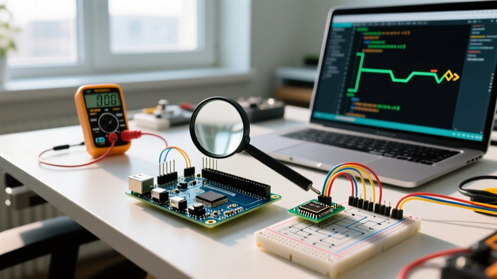
When integrating a hall effect encoder into a system with stepper drivers (like the TMC2209 or A4988), electromagnetic interference (EMI) is the primary enemy. The high-frequency PWM switching (20kHz - 50kHz) from the motor drivers induces common-mode noise on the Arduino's 5V rail, which translates directly into angular jitter on the encoder's ADC.
The 'Clean Power' Architecture
Do not power your precision Hall IC from the Arduino's onboard 5V regulator if motors are active. Instead:
- Use a dedicated low-dropout (LDO) regulator, such as the LD1117V33, powered directly from your main DC bus (e.g., 12V or 24V).
- Place a 100nF X7R ceramic capacitor and a 10µF tantalum capacitor as close to the VCC and GND pins of the Hall IC as physically possible (within 2mm).
- Route the I2C/SPI traces away from the motor phase wires. If they must cross, ensure they cross at a strict 90-degree angle to minimize inductive coupling.
Frequently Asked Questions
Can I use a standard potentiometer knob on a Hall sensor?
No. Standard potentiometers contain their own internal resistive wiper. To use a physical knob with a Hall IC, you must mount a diametrically magnetized cylinder to the bottom of the knob's shaft and position the IC directly beneath it.
Why is my AS5600 outputting exactly 4095 or 0?
This indicates the magnetic field is either too weak (air gap > 2.5mm) or too strong (magnet saturating the silicon). Check your magnet orientation and use a non-magnetic spacer (like PLA plastic or brass) to dial in the exact 1.5mm air gap.
Does temperature affect Hall encoder accuracy?
Yes, neodymium magnets lose roughly 0.1% of their field strength per degree Celsius increase. However, high-end ICs like the TLE5012B and AS5048A feature internal temperature compensation algorithms that adjust the ADC gain dynamically, keeping angular error below 0.1 degrees across a -40°C to +125°C range.