
Why You Must Test Electronic Component Parts Out of the Box
Unboxing a beginner electronics kit—like the popular Elegoo Super Starter Kit or the RexQualis Mega2560 bundle—is a thrilling milestone for any DIY enthusiast. However, a frustrating reality awaits many novices: the 'Dead on Arrival' (DOA) component. Mass-produced, budget-friendly kits sourced from overseas often suffer from poor quality control. A single faulty MOSFET or a leaky electrolytic capacitor can cause hours of agonizing debugging when your circuit fails to power on.
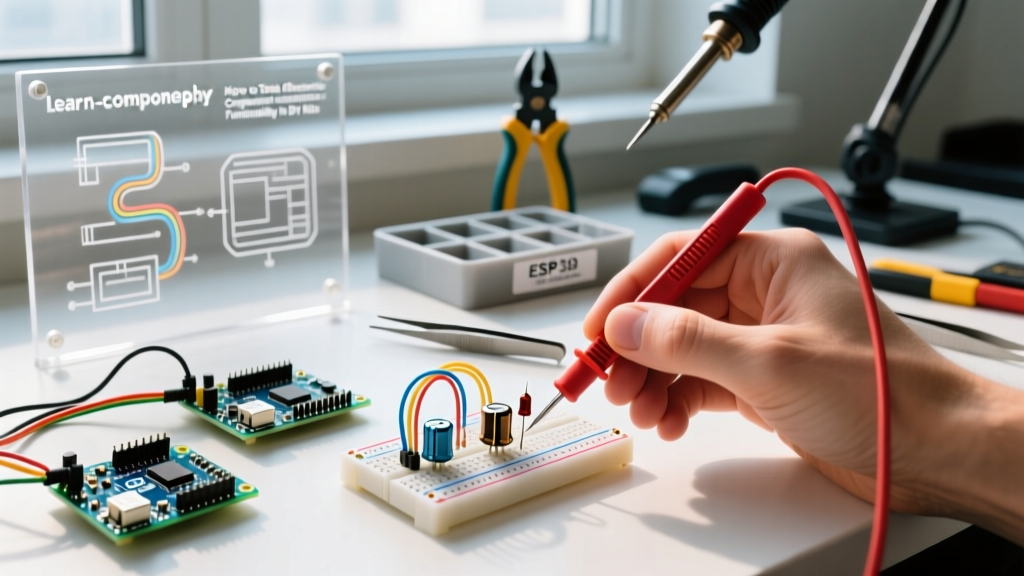
Learning how to test electronic component parts before you insert them into your breadboard is not just a best practice; it is a mandatory skill for efficient prototyping. By verifying your inventory upfront, you isolate hardware failures from logical wiring errors, saving you immense time and frustration. This guide will walk you through the exact methodologies, tools, and specific measurements required to vet the contents of your beginner kit in 2026.
The Right Tool for the Job: Multimeter Selection
You cannot accurately test electronic component health without a reliable Digital Multimeter (DMM). While the $10 freebie meters from hardware stores might check a car battery, they lack the precision and safety features required for sensitive PCB components. According to SparkFun's comprehensive multimeter tutorial, a beginner needs a meter with auto-ranging, a diode test function, and basic capacitance measurement.
| Model | Approx. Price | DC Voltage Accuracy | Best Feature for Beginners |
|---|---|---|---|
| AstroAI DM6000AR | $35.00 | ±(0.5% + 3) | Excellent auto-ranging speed and built-in magnetic hanger. |
| Klein Tools MM400 | $48.00 | ±(0.7% + 2) | Rugged build quality, survives drops off the workbench. |
| Uni-T UT61E+ | $75.00 | ±(0.1% + 5) | True RMS and high-resolution capacitance testing. |
Pro-Tip: If your kit includes a lot of ceramic capacitors, consider adding an LCR-T4 Transistor/Capacitor Tester (approx. $25) to your arsenal. Standard DMMs struggle to read capacitance values below 10nF accurately.
The Pre-Flight Testing Matrix
Before diving into the specifics, use this quick-reference matrix to set up your multimeter for the most common components found in beginner kits.
| Component | DMM Setting | Probe Placement | Expected Result / Failure Mode |
|---|---|---|---|
| Resistor | Ohms (Ω) | Across both legs (polarity agnostic) | Within 5% of color code. Fail: Reads 'OL' (Open). |
| Electrolytic Capacitor | Capacitance (F) | Red to +, Black to - | Within 20% of printed value. Fail: Reads 0 or short. |
| LED | Diode Test | Red to Anode (long), Black to Cathode | 1.8V - 3.3V forward drop. Fail: Reads 'OL' or 0V. |
| NPN Transistor | hFE (Gain) | Insert into DMM hFE socket (E, B, C) | hFE between 100 - 800. Fail: Reads 0 or 1. |
| Pushbutton Switch | Continuity (Beep) | Across diagonal pins | Beeps when pressed. Fail: Always beeps or never beeps. |
Step-by-Step Verification Guide
1. Resistors: Beyond the Color Bands
Beginner kits are packed with 1/4W carbon film resistors. While you can read the color bands (e.g., Brown-Black-Orange-Gold for 10kΩ at 5% tolerance), manufacturing defects or heat damage during kit packaging can alter their resistance. Set your DMM to the Ohms (Ω) setting. For a 10kΩ resistor, your meter should read between 9.5kΩ and 10.5kΩ.
According to the All About Circuits resistor experiments guide, you must ensure your fingers are not touching both metal probe tips simultaneously while measuring. The human body has a resistance of roughly 50kΩ to 100kΩ; touching the probes will create a parallel circuit, skewing your high-value resistor readings lower than they actually are.
2. Capacitors: Spotting Leaks and Shorts
Cheap electrolytic capacitors (the cylindrical components with a stripe) are notorious for drying out or suffering from internal shorts. If you apply power to a shorted 10µF 50V capacitor on a breadboard, it can pop violently, destroying your microcontroller.
- Visual Inspection: Check the top vent. If it is bulging, discard it immediately.
- Short Test: Set your DMM to continuity mode. Touch the probes to the legs. A healthy capacitor will show a brief spike as it charges, then return to 'OL' (Open Line). If it continuously beeps, the internal dielectric has failed, and it is a dead short.
- Capacitance Test: Switch to the Capacitance setting. Ensure you discharge the capacitor first by shorting its legs with a 1kΩ resistor. A 100µF capacitor should read between 80µF and 120µF (standard ±20% tolerance).
3. LEDs and Diodes: Chasing the Forward Voltage
Never test an LED using the continuity/beep setting; the open-circuit voltage of a continuity test is often too low to forward-bias the LED junction, leading you to falsely believe the LED is dead. Instead, use the dedicated Diode Test mode (indicated by a diode symbol on the dial).
- Red/Yellow/Green LEDs: Should display a forward voltage drop between 1.8V and 2.2V.
- Blue/White/UV LEDs: Require higher energy and will display a drop between 2.8V and 3.3V.
- Failure Mode: If the meter reads '0.000', the LED is internally shorted. If it reads 'OL' in both directions, the internal bond wire has snapped.
4. Bipolar Junction Transistors (BJTs): The Pinout Trap
Testing transistors like the ubiquitous 2N2222 or BC547 is where most beginners fail, primarily due to pinout confusion. As detailed in Fluke's guide on testing transistors, you must know the exact Emitter-Base-Collector (EBC) arrangement.
⚠️ CRITICAL BEGINNER TRAP: If you hold a 2N2222 TO-92 transistor with the flat side facing you, the pins from left to right are Emitter, Base, Collector. However, if you hold a BC547 the exact same way, the pins are Collector, Base, Emitter. Always check the specific datasheet before inserting it into your multimeter's hFE testing socket!
Insert the transistor into the DMM's hFE socket. A healthy BC547 NPN transistor will show an hFE (DC current gain) between 110 and 800. If it reads '0' or '1', the junction is blown. If your kit includes MOSFETs (like the IRF520), standard DMM hFE tests will not work; you must test them using the diode mode across the Drain and Source to check the internal body diode.
5. Integrated Circuits: The VCC-to-GND Short Check
You cannot test the internal logic of a 555 Timer or an ATmega328P microcontroller with just a multimeter. However, you can test for catastrophic internal failures. Set your DMM to continuity mode. Place the black probe on the GND pin (Pin 1 on a 555 Timer, Pin 8 on an ATmega328P DIP package) and the red probe on the VCC pin.
The Verdict: It should read 'OL'. If the multimeter beeps, the IC has suffered a catastrophic internal short circuit (often caused by ESD damage during cheap manufacturing or shipping). Throw it away; it will instantly drain your power supply and potentially overheat your breadboard wires if powered.
Organizing Your Verified Inventory
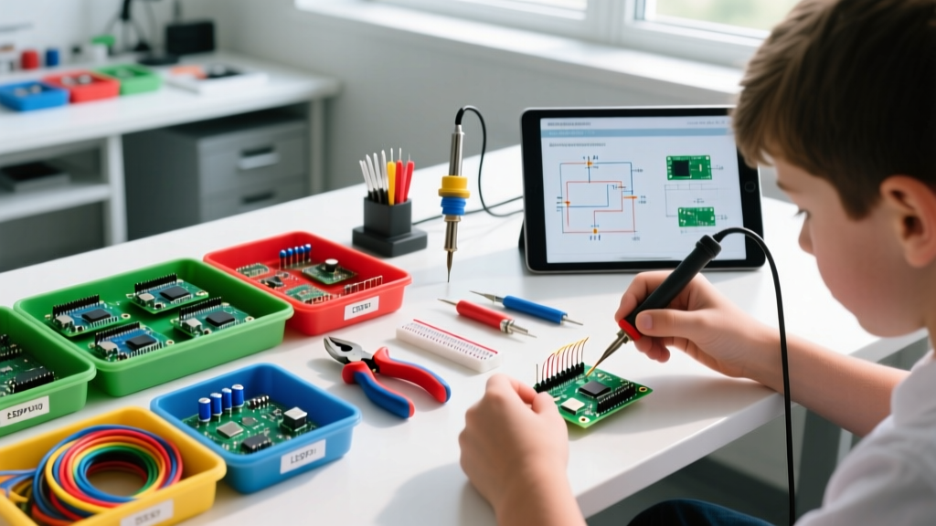
Once you have successfully tested your electronic component batch, do not toss them back into the mixed plastic bags they arrived in. Invest in a multi-compartment storage box (like the Plano 1374-00, roughly $18). Label the compartments by component type and value. By taking 45 minutes to test and sort your beginner kit on day one, you guarantee that every future circuit failure is a learning opportunity about your wiring or code, rather than a wild goose chase for a defective 10-cent resistor.