
The 2026 Landscape of Passive Electronic Component Selection
While microcontrollers and power management ICs often dominate the bill of materials (BOM) budget, the humble passive electronic component makes up over 80% of the total part count on a modern printed circuit board. In 2026, as edge AI accelerators, 6G RF front-ends, and high-density automotive sensors push the boundaries of PCB design, treating passives as mere 'filler' parts is a recipe for catastrophic field failures. Selecting the correct passive electronic component requires a deep understanding of parasitic effects, thermal derating, material science, and modern supply chain realities.
This guide bypasses basic textbook definitions and dives straight into the advanced selection criteria, failure modes, and BOM optimization strategies required for professional-grade hardware engineering.
Resistors: Beyond Basic Ohm's Law
When selecting a resistor for a precision analog front-end or a high-speed digital termination network, the nominal resistance value is only the starting point. Engineers must evaluate the Temperature Coefficient of Resistance (TCR), parasitic capacitance, and high-frequency behavior.
Thick Film vs. Thin Film vs. Metal Foil
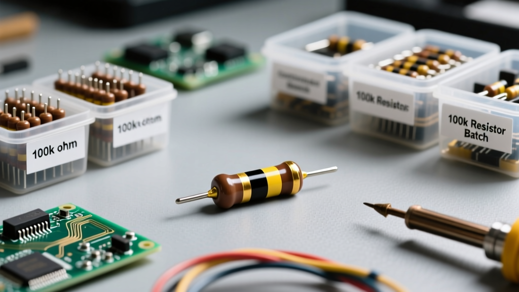
The construction method of a resistor dictates its performance envelope and cost. In 2026, standard thick film resistors (like the ubiquitous Vishay CRCW series) remain the workhorse for pull-ups, pull-downs, and LED current limiting. However, they exhibit poor TCR (typically ±100 to ±200 ppm/°C) and high parasitic inductance due to their laser-trimmed serpentine geometry.
- Thick Film: Best for general-purpose digital logic. Cost: ~$1.50 per 10,000 reel (0402 package). TCR: ±100 ppm/°C.
- Thin Film: Essential for precision ADCs, DACs, and transimpedance amplifiers. Models like the Susumu RG series offer TCRs as low as ±5 ppm/°C and significantly lower current noise. Cost: ~$15.00 per 10,000 reel.
- Metal Foil: Used in laboratory-grade instrumentation and aerospace. TCR: <±1 ppm/°C. Cost: $1.00 to $5.00+ per individual unit.
High-Frequency Parasitics
At frequencies above 1 GHz, a standard 0402 thick film resistor ceases to act as a pure resistance. The serpentine laser cuts create parasitic inductance, while the proximity of the terminations creates parasitic capacitance. For 5G/6G RF matching networks and high-speed SerDes termination, engineers must specify specialized high-frequency thin film resistors with optimized geometries that minimize the parasitic LC resonance.
Capacitors: Navigating the MLCC Maze
Multilayer Ceramic Capacitors (MLCCs) are the most complex passive electronic component to specify correctly. The primary trap for junior engineers is ignoring DC bias derating and temperature coefficients, leading to power supply instability and unexpected oscillation.
The DC Bias Derating Trap
Class II dielectrics (X5R, X7R) are formulated from barium titanate, a ferroelectric material. When a DC voltage is applied, the electric domains align and 'lock' into place, severely reducing the material's permittivity. A 10µF, 6.3V X5R 0805 MLCC might only provide 3.5µF of actual capacitance when 4V of DC bias is applied. Always use manufacturer simulation tools, such as the Murata SimSurfing Tool, to verify effective capacitance under your exact operating voltage and temperature conditions.
Expert Warning: Never design a buck converter output filter based solely on the nominal capacitance printed on the reel. If your DC bias derates your 47µF MLCC bank down to 15µF, your control loop phase margin will collapse, resulting in severe output voltage ringing and potential catastrophic failure of downstream logic.
Piezoelectric Microphonics in Audio Circuits
The same barium titanate crystal structure that causes DC bias derating also exhibits a strong piezoelectric effect. In high-gain audio amplifiers or sensitive RF receivers, mechanical vibrations from the PCB can cause the MLCC to generate microphonic voltage noise (often called 'singing capacitors'). To mitigate this, designers must either use Class I (C0G/NP0) dielectrics, which are not piezoelectric, or specify MLCCs with specialized soft-termination and interposer substrates that mechanically decouple the component from the PCB.
| Dielectric Class | EIA Code | Temperature Stability | DC Bias Effect | Primary Application |
|---|---|---|---|---|
| Class I | C0G / NP0 | ±30 ppm/°C (Exceptional) | None | RF Matching, Audio, Precision Timing |
| Class II | X7R | ±15% (-55°C to +125°C) | High (Up to 70% loss) | Decoupling, General Power Filtering |
| Class II | X5R | ±15% (-55°C to +85°C) | High (Up to 80% loss) | Consumer Electronics, Low-Cost Decoupling |
| Class III | Y5V | +22% / -82% (Terrible) | Extreme (Up to 90% loss) | Legacy/Obsolete (Avoid in modern designs) |
Inductors and Ferrite Beads: Managing EMI and Power
Inductors store energy in a magnetic field, but their physical construction introduces significant parasitic resistance (DCR) and parallel capacitance. When selecting an inductor for a switching regulator, two current ratings must be rigorously evaluated:
- Saturation Current (Isat): The DC current at which the inductor's core material saturates, causing inductance to drop (typically defined at a 20% or 30% drop). Exceeding Isat causes a massive spike in peak switch current, potentially destroying the MOSFET.
- RMS Current (Irms): The continuous DC current that causes the component's temperature to rise by 40°C. Exceeding Irms leads to thermal degradation of the winding enamel and eventual open-circuit failure.
For modern high-density power supplies, shielded composite core inductors (such as the Coilcraft XEL series) are preferred. They offer a soft saturation curve, meaning inductance decreases gradually rather than abruptly, providing a wider safe operating area (SOA) for the power stage. Furthermore, their shielded construction minimizes magnetic flux leakage, which is critical for passing CISPR 25 EMI standards in automotive environments.
Ferrite Beads for High-Frequency Noise
Ferrite beads are not standard inductors; they are highly lossy, resistive components at high frequencies. When selecting a ferrite bead for power rail filtering, look at the impedance curve, not just the DC resistance. A bead rated for 1000Ω at 100MHz will effectively turn high-frequency digital switching noise into harmless heat. However, engineers must ensure the bead's DC bias rating exceeds the rail's maximum current draw, as ferrite materials saturate very easily, rendering them useless for EMI filtering if overdriven.
PCB Assembly and Miniaturization Realities
The push for smaller wearable devices and dense IoT nodes has driven the industry toward 0201 (0.6mm x 0.3mm) and 01005 (0.4mm x 0.2mm) passive packages. While 01005 components save valuable board real estate, they introduce severe Design for Manufacturing (DFM) challenges.
- Tombstoning: The 01005 passive electronic component is so light that unequal wetting forces during reflow can literally stand the part up on one end. This requires hyper-precise solder paste stencil design, often utilizing home-plate or U-shaped aperture reductions.
- Inspection Limits: Automated Optical Inspection (AOI) systems struggle with 01005 parts, often requiring expensive 3D X-ray inspection to verify hidden solder joints, especially on bottom-termination components (BTCs).
- Rework Impossibility: Hand-reworking a failed 01005 MLCC under a microscope is nearly impossible without specialized micro-soldering equipment and highly trained technicians. Design for testability (DFT) and high first-pass yield are non-negotiable when using these micro-passives.
BOM Optimization and Supply Chain Strategy
In the post-2024 supply chain environment, relying on a single manufacturer for critical passives is a severe business risk. Automotive-grade passives (AEC-Q200 certified) frequently experience lead times exceeding 30 weeks during demand surges. Professional hardware teams implement 'form-fit-function' (FFF) alternate part numbers directly in their ERP systems. When specifying an MLCC, do not just list a Murata part number; validate and list equivalent TDK, Samsung, and Yageo part numbers with identical capacitance, voltage, dielectric, and package size to ensure procurement can source from available inventory without halting the production line.
Frequently Asked Questions (FAQ)
Can I mix X7R and X5R capacitors in the same power rail decoupling network?
Yes, but with caution. X7R offers a wider temperature range (-55°C to +125°C) compared to X5R (-55°C to +85°C). If your device operates in an industrial or automotive environment where ambient temperatures exceed 85°C, the X5R capacitors will experience severe capacitance loss and accelerated aging. Always match the dielectric temperature rating to the worst-case thermal profile of your enclosure.
Why are my precision resistors drifting over time?
All resistors exhibit Long-Term Stability (LTS) drift, usually measured in percentage change after 1,000 hours at rated load and 70°C. Thick film resistors can drift by 1% or more, while precision thin film resistors are engineered to drift less than 0.1%. If your application requires absolute stability over a 10-year lifespan (e.g., medical metering), you must specify resistors with guaranteed LTS data and potentially implement software auto-calibration routines.
Do I need to derate the voltage rating of my MLCCs?
Absolute maximum voltage ratings on MLCCs include a safety margin, but industry best practice dictates a 50% derating rule for Class II dielectrics (X7R/X5R) to mitigate DC bias capacitance loss and ensure long-term reliability against dielectric breakdown. For Class I (C0G) dielectrics, which do not suffer from DC bias effects, a 20% derating margin is generally sufficient for standard commercial applications.