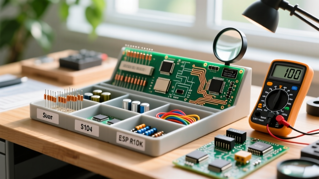

Every electronics hobbyist and engineer eventually faces the same chaotic hurdle: a plastic bin full of unsorted, cryptically marked components. Whether it is a mixed grab-bag of surface-mount devices (SMD) or a tangled web of through-hole resistors, deciphering electronics component markings is a foundational skill that separates novices from proficient circuit designers. Instead of just memorizing charts, we are going to use a Project-Based Learning approach. In this guide, you will build a professional-grade 'Component Decoding and Sorting Station' while systematically learning to identify, verify, and catalog every major component type.
Project Overview: The Sorting Station Build
Before diving into the code-breaking, let us outline the physical deliverable for this project. You will need to assemble a dedicated workspace to handle micro-components. As of 2026, the cost of entry for high-quality prototyping organization has dropped significantly.
- Storage: Akro-Mils 10164 64-Drawer Cabinet (Approx. $38.50). The angled drawers prevent static buildup and allow easy scooping with tweezers.
- Optics: Plugable USB2-MICRO-250X Digital Microscope (Approx. $29.99). Essential for reading laser-etched SMD codes.
- Labeling: Brother PT-D210 Label Maker with 12mm laminated tape (Approx. $39.99). Laminated tape prevents isopropyl alcohol (IPA) from dissolving your labels during PCB cleaning.
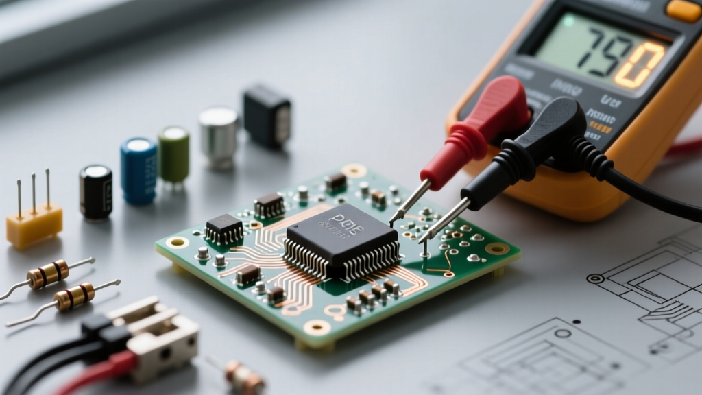
- Verification: A reliable bench multimeter (e.g., Brymen BM235 or Uni-T UT61E+) for capacitance and resistance validation.
Phase 1: Through-Hole Resistor & Capacitor Sorting
Your first project milestone is sorting a standard 1,000-piece mixed through-hole resistor kit (typically $8–$12 online). While automated sorters exist, manually decoding the color bands builds the muscle memory required for rapid circuit debugging.
Decoding the Color Bands
Most standard kits use 4-band or 5-band resistors. The critical E-E-A-T detail here is the tolerance band, which is always spaced slightly further apart from the value bands. According to SparkFun's Resistor Tutorial, the color of this isolated band dictates the precision: Gold is ±5%, Silver is ±10%, and Brown is ±1%. If you are sorting precision metal-film resistors, you will almost exclusively see Brown (1%) or Red (2%) tolerance bands.
Pro-Tip for the Sorting Station: Do not rely solely on visual color decoding for critical analog circuits (like op-amp feedback loops). Always verify a 10-sample batch from your sorted bins with your multimeter. Lighting conditions and colorblindness can easily cause a 470Ω (Yellow-Violet-Brown) to be misread as a 270Ω (Red-Violet-Brown).
Phase 2: Cracking the SMD Code Matrix
Surface-mount technology (SMT) introduces a massive layer of complexity. Because components like 0603 and 0402 resistors are physically tiny, manufacturers use shorthand electronics component markings. Set up your USB microscope and connect it to your monitor to begin Phase 2.
Standard 3-Digit and 4-Digit Codes
For standard thick-film SMD resistors, the first two (or three) digits represent the significant figures, and the last digit is the multiplier (number of zeros).
- 103: 10 × 10³ = 10,000Ω (10kΩ) — Typically 5% tolerance.
- 1002: 100 × 10² = 10,000Ω (10kΩ) — Typically 1% tolerance.
Edge Case Warning: As of 2026, 0201 and 0402 size resistors often feature no markings at all due to physical space constraints. You must keep these in their original taped reels until the exact moment they are placed on the PCB.
The EIA-96 Standard for Precision SMDs
High-precision 1% SMD resistors often use the EIA-96 marking system, which consists of two numbers followed by a letter. The numbers correspond to a lookup table (e.g., '01' = 100, '68' = 499), and the letter is the multiplier. Refer to Wikipedia's EIA-96 Standard Documentation for the full matrix. Below is a quick-reference table for your sorting station:
| Marking | Significant Digits (Value) | Multiplier Letter | Final Resistance |
|---|---|---|---|
| 01C | 100 | C (×10²) | 10.0 kΩ |
| 68X | 499 | X (×10⁻¹) | 49.9 Ω |
| 76E | 604 | E (×10⁴) | 6.04 MΩ |
Phase 3: Semiconductor and IC Markings
Integrated Circuits (ICs) and discrete semiconductors carry the most dense information. When sorting SOIC-8, SOT-23, or QFP packages, you are looking for three distinct data points: The Manufacturer Logo, the Part Number, and the Date/Lot Code.
SOT-23 Transistor Cryptography
The SOT-23 package is notorious for using 2- or 3-character codes instead of full part numbers. You will need a digital datasheet library or an app like 'SMD Code' on your smartphone. Here are three of the most common markings you will encounter in your sorting project:
- '1AM' = MMBT3904 (General Purpose NPN BJT)
- '2A' = MMBT3906 (General Purpose PNP BJT)
- '702' or 'J7' = 2N7002 (N-Channel Logic Level MOSFET)
IC Date Codes and MSL Degradation
Most ICs feature a 4-digit date code in YYWW format (Year, Week). For example, '2345' means the chip was manufactured in the 45th week of 2023. Why does this matter for your sorting station? Moisture Sensitivity Level (MSL). According to IPC/JEDEC J-STD-020 standards, MSL 3 and above components (like many QFP microcontrollers) have a limited floor life once exposed to ambient humidity. If you salvage parts from old boards or buy surplus stock with date codes older than 2 years, you must bake them in a reflow oven or dedicated component dryer (at 125°C for 4-8 hours) before reflow soldering, otherwise trapped moisture will cause the 'popcorn effect,' cracking the IC package from the inside out.
Phase 4: Polarity Markings and Failure Mode Analysis
Misinterpreting polarity markings is the fastest way to destroy a prototype. Your sorting station must have strict, color-coded separation for polarized components.
The Tantalum vs. Aluminum Electrolytic Trap
This is a classic failure mode edge case that catches many engineers off guard. The visual indicators for polarity are completely reversed between these two common capacitor types:
- Aluminum Electrolytic (Cylindrical): The painted stripe with minus signs indicates the NEGATIVE (Cathode) terminal.
- Solid Tantalum (SMD Rectangular): The painted stripe or bar indicates the POSITIVE (Anode) terminal.
Critical Safety Warning: Reversing the polarity on an aluminum electrolytic capacitor will cause it to vent electrolyte and pop. However, reversing the polarity on a Tantalum capacitor is far more dangerous. It creates a low-impedance short circuit that leads to rapid thermal runaway, often resulting in literal ignition and flames on your PCB. Always verify the NASA Electronic Parts and Packaging (NEPP) Program guidelines on tantalum derating and polarity inspection before powering up a new board.
Diode and LED Cathode Indicators
For SMD diodes (like the SMA/SMB packages), the white or black band always denotes the Cathode (Negative). For unmarked SMD LEDs, use your multimeter's diode test mode. The lead that allows current to flow (showing a forward voltage drop, typically 1.8V to 3.3V) is the Anode; the multimeter's red probe will be touching the Anode pad during a successful reading.
Project Deliverable: Executing the Sorting Workflow
With your knowledge of electronics component markings established, execute the following workflow to finalize your sorting station:
- Inspect: Place the component under the USB microscope. Identify the package type (e.g., 0805, SOT-23, SOIC-8).
- Decode: Read the marking. Use the EIA-96 chart for precision resistors, or an SMD code database for active semiconductors.
- Verify: Spot-check 5% of the batch with your multimeter to ensure the grab-bag vendor did not mislabel the reels.
- Label: Use the Brother PT-D210 to print a label featuring the Value/Part Number, Package Size, and Tolerance/Voltage rating. (e.g., '10kΩ 1% 0603' or '100nF 50V 0805 X7R').
- Store: Place the components in the Akro-Mils drawer, ensuring polarized parts are oriented in the same direction for rapid visual inspection during future PCB assembly.
By completing this project, you have not only organized your lab but also internalized the critical visual language of electronic components. The next time you are debugging a faulty PCB or designing a new schematic, reading electronics component markings will be second nature, saving you hours of cross-referencing and preventing catastrophic polarity failures.