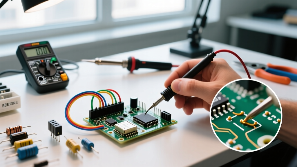

The True Cost of Electronic Component Failures in Prototyping
There is a distinct, acrid smell that every hardware engineer knows intimately: the scent of vaporized silicon and burning flux. In the rush to prototype a new DC power circuit, electronic component failures are often treated as an unavoidable rite of passage. However, as we navigate the component supply chain and design complexities of 2026, treating failures as 'inevitable' is a costly mistake. A single failed prototype iteration can cost upwards of $150 to $300 in engineering debug time, not to mention the delayed time-to-market. By contrast, implementing robust protection schemes and proper component derating costs pennies per board.
This circuit application tutorial moves beyond basic theory. We will dissect the specific physical and electrical mechanisms that cause catastrophic failures in DC power circuits, providing actionable PCB layout rules, exact component substitutions, and step-by-step protection topologies to ensure your designs survive first-power-on.
Top 3 Electronic Component Failures in DC Applications
1. Ceramic Capacitor Dielectric Breakdown (MLCC Flex Cracking)
Multilayer Ceramic Capacitors (MLCCs) are the backbone of modern decoupling, but they are mechanically fragile. The most insidious of all electronic component failures in high-density boards is flex cracking. When a PCB bends—even by as little as 2mm during connector insertion or board depanelization—the mechanical strain transfers to the brittle barium titanate dielectric inside the MLCC. This creates micro-fractures that eventually short-circuit, causing catastrophic thermal runaway.
- The Material Trap: X7R and X5R dielectrics exhibit piezoelectric effects and are highly susceptible to mechanical stress. C0G/NP0 dielectrics are vastly more stable but offer lower capacitance densities.
- The Size Factor: Larger packages like 1206 and 0805 are significantly more prone to flex cracking than 0402 or 0201 packages because the distance between the rigid solder joints is wider, creating a larger lever arm for mechanical strain.
- PCB Layout Fix: Never place large MLCCs parallel to V-score lines or near heavy connectors. According to guidelines published by the NASA Electronic Parts and Packaging (NEPP) program, components should be oriented perpendicular to the expected board bend axis, and kept at least 5mm away from board edges and mounting holes.
2. MOSFET Thermal Runaway and Gate Drive Mismatches
A classic prototyping error involves driving a standard MOSFET directly from a 3.3V microcontroller GPIO. Take the ubiquitous IRFZ44N. While its datasheet lists a Gate-Source Threshold Voltage (Vgs(th)) of 2.0V to 4.0V, this is merely the voltage at which the device begins to conduct a negligible 250µA. To achieve the advertised low Rds(on) of 17.5mΩ, the IRFZ44N requires a Vgs of 10V.
If you drive it with 3.3V from an ESP32, the MOSFET operates in its linear (ohmic) region rather than fully saturating. The Rds(on) might spike to over 2Ω. At just 1A of continuous drain current, the MOSFET will dissipate 2W (P = I²R) without a heatsink, rapidly exceeding its junction temperature limit and resulting in a short-circuit failure.
Expert Rule of Thumb: Always select logic-level MOSFETs for 3.3V or 5V microcontroller drives. Look for a guaranteed Rds(on) specification at Vgs = 2.5V or 4.5V. The IRLB8721 (Vgs(th) max 1.9V, Rds(on) 8.7mΩ at 4.5V) is a superior, fail-safe alternative for 3.3V logic applications.
3. Electrolytic Capacitor Dry-Out and ESR Spikes
Aluminum electrolytic capacitors are essential for bulk energy storage in buck and boost converters, but they contain a liquid electrolyte that slowly vaporizes over time, especially when subjected to high ripple currents. The power dissipated inside a capacitor is calculated as P = I_ripple² × ESR (Equivalent Series Resistance). If a generic 85°C capacitor with a high ESR of 150mΩ is used in a switching regulator outputting 2A of ripple current, it will internally dissipate 0.6W. This self-heating accelerates electrolyte evaporation, creating a positive feedback loop that ends in a vented, bulging capacitor.
The Fix: Always specify 'Low-ESR' or 'High-Ripple' series capacitors rated for 105°C. For example, the Panasonic FR series (e.g., 35FR100M) offers an ESR of just 12mΩ at 100kHz and a ripple current rating of 1.2A, drastically reducing internal heating and extending operational life by a factor of 10 compared to generic alternatives.
Failure Mode Matrix: Symptoms, Root Causes, and PCB Fixes
| Component | Failure Symptom | Root Cause Mechanism | Actionable PCB / Design Fix |
|---|---|---|---|
| MLCC (X7R) | Dead short, board scorching near cap | Mechanical flex cracking causing internal electrode short | Use smaller packages (0402), add flex-relief slots, orient perpendicular to bend lines. |
| N-Channel MOSFET | Overheating at low current, GPIO pin damage | Insufficient Vgs drive leaving FET in linear region; Miller effect ringing | Use logic-level FETs (IRLB8721); add 10kΩ gate pull-down and 10Ω gate series resistor. |
| Electrolytic Cap | Venting, bulging top, loss of output regulation | High ripple current causing internal heating and electrolyte boil-off | Specify 105°C low-ESR series (Panasonic FR/FM); parallel with 100nF ceramic for high-freq. |
| TVS Diode | Short circuit, blowing upstream fuses | Clamping voltage exceeded by sustained overvoltage (not transient) | Pair TVS with a series PTC resettable fuse or crowbar SCR circuit for sustained faults. |
Step-by-Step Tutorial: Designing a Fail-Safe 12V to 5V Buck Converter
To demonstrate how to preemptively engineer against electronic component failures, let us walk through the input and switching node protection of a 12V to 5V, 3A buck converter design. We will focus on the three most critical vulnerability points.
Step 1: Implementing Robust Input Protection
Automotive and industrial 12V rails are notoriously noisy, plagued by load-dump transients that can spike to 40V or more. A standard 5V buck IC will instantly fail under these conditions.
- Select the TVS Diode: Choose a unidirectional Transient Voltage Suppression diode like the Littelfuse SMAJ15A. Its breakdown voltage is 16.7V, and it clamps transients safely below the 40V absolute maximum rating of most modern wide-Vin buck controllers.
- Add a PTC Fuse: A TVS diode can only absorb energy for milliseconds. If a sustained 24V fault occurs, the TVS will overheat and fail short. Place a 2A PTC resettable fuse (e.g., Bourns MF-MSMF200-2) in series before the TVS. The TVS clamps the spike, and if the fault persists, the PTC trips, protecting the TVS and the downstream circuitry.
Step 2: Taming Switching Node Ringing with an RC Snubber
The switching node (SW) of a buck converter is a high dV/dt environment. Parasitic inductance from PCB traces and the MOSFET's internal capacitance form an LC tank circuit, causing high-frequency ringing. This ringing can exceed the MOSFET's drain-source breakdown voltage (Vds), leading to avalanche breakdown.
- Measure the Ringing: Using an oscilloscope with a spring-ground probe tip (to minimize loop inductance), measure the ringing frequency at the SW pin. Let us assume you measure a 50MHz ring.
- Calculate the Snubber: The goal is to critically damp this resonance. A standard starting point is an RC snubber consisting of a 10Ω resistor in series with a 470pF capacitor, placed as physically close to the SW pin and PGND as possible. Refer to Texas Instruments Power Management design resources for detailed snubber optimization spreadsheets.
Step 3: Thermal Via Stitching for IC Ground Pads
Modern buck converters utilize QFN or LGA packages where the primary thermal dissipation path is the exposed pad on the bottom of the IC. If this pad is soldered to a solid copper pour without thermal vias, the heat becomes trapped.
The Layout Rule: Place an array of 0.3mm drilled thermal vias in a 1mm grid pattern directly under the IC's thermal pad. Cap the vias on the opposite side with a solid ground plane. This creates a low-thermal-resistance conduit to the inner and bottom copper layers, reducing the junction-to-ambient thermal resistance (θJA) by up to 40%.
Essential Bench Tools for Root Cause Analysis
When electronic component failures do occur, visual inspection is rarely enough. You need tools that reveal the invisible physics of the failure.
- Thermal Imaging: A micro-short in an MLCC or a biased MOSFET will generate localized heat long before the component catastrophically fails. Utilizing a tool like the FLIR C5 or referencing Keysight Technologies' oscilloscope fundamentals for power rail analysis allows you to spot thermal anomalies. A temperature delta of just 10°C above ambient on a ceramic capacitor under no-load conditions is a massive red flag for dielectric leakage.
- True-RMS Multimeter with Peak Capture: Standard multimeters average out voltage spikes. A meter with a 250µs peak capture function (like the Fluke 87V) is essential for catching the microsecond inrush currents that blow undersized protection fuses during power-on.
- LCR Meter: To verify if an electrolytic capacitor has degraded, do not just measure capacitance. Measure the ESR at 100kHz. A 1000µF capacitor that reads 1000µF but has an ESR of 1.5Ω is effectively dead in a switching circuit and must be replaced.
Frequently Asked Questions (FAQ)
Why do my 0402 resistors keep cracking during PCB assembly?
While 0402 resistors are less prone to flex cracking than MLCCs, they can crack if the PCB solder paste stencil is too thick. Excess solder creates a highly rigid, asymmetric fillet that exerts sheer stress on the ceramic body during thermal cycling. Reduce your stencil thickness to 4 mils (0.1mm) and ensure the pad geometry matches the IPC-7351 standard for the specific resistor termination type.
Can I use a Zener diode instead of a TVS diode for transient protection?
No. While both rely on reverse-breakdown physics, Zener diodes are designed for continuous voltage regulation and have very low surge current capabilities (typically a few watts). A TVS diode is engineered with a massive silicon junction specifically to absorb hundreds or thousands of watts of transient energy for milliseconds. Using a Zener for load-dump protection will result in an immediate, explosive failure.
How does altitude affect electronic component failures?
At higher altitudes, the air density drops, which severely degrades convective cooling. A heatsink that performs perfectly at sea level may see a 30% reduction in thermal dissipation at 10,000 feet. Furthermore, the reduced dielectric strength of thin air increases the risk of arc tracking across high-voltage PCB traces. If your application operates above 3,000 meters, you must increase conformal coating thickness, widen high-voltage creepage distances, and heavily derate power components.